")
Description
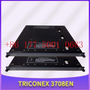
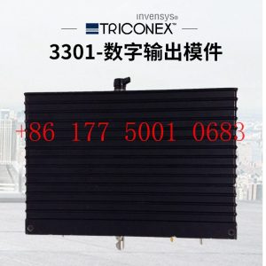
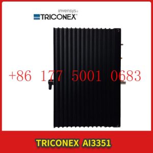
PS8310 TRICONEX nput/output communication card
PS8310 TRICONEX nput/output communication card
Module Clips Drive controller servo motor
Contact: Mr. Lai
Wechat:17750010683
Whats app:+86 17750010683
Skype:+86 17750010683
QQ: 3221366881
3221366881@qq.com
What IO combinations can a mini PLC combine with to achieve automated control?
At present, there are two main design modes for controllers like PLC, one is integrated design and the other is modular design. From the name, we can feel that there are two different PLCs, one that cannot be disassembled and the other that can be disassembled. Due to the fact that the main control module and IO module of the modular PLC can be spliced as needed, its volume and weight are usually very small, and we cannot call it a mini PLC too much. So, what IO combinations can such a small gadget combine with to achieve automation control? Let”s take a brief inventory:PS8310 TRICONEX nput/output communication card
1. Firstly, there is the digital quantity acquisition IO module, which is used to collect digital quantity information. Typical examples include counter IO, PNP type digital quantity acquisition IO, NPN type digital quantity acquisition IO, etc.
2. Then there is the digital output IO module, which is used to send digital instructions. The most typical example is PWM output IO, which can output pulse signals to control servo motors or stepper motors for operation.
3. After talking about digital IO, let”s talk about analog IO. Analog signal acquisition type IO includes voltage signal acquisition, current signal acquisition, and temperature signal acquisition. The IO for collecting temperature signals includes PT100, PT1000, and various thermocouple temperature acquisition modules.
4. Finally, there are analog output IO, as well as output current signals and voltage signals.
In addition to the above IO modules, our modular PLC also supports extended communication interfaces, further enhancing the equipment”s scalability.
Module Input/Output (I/O) KnowledgePS8310 TRICONEX nput/output communication card
Module Input/Output (I/O) Knowledge
I think it”s necessary to talk about the sorting of the input and output ports of the module. Generally, we can divide it into IO functional division and IO specifications.
The purpose of the former is mainly to convert all functions into actual division into MCU IO ports, while the purpose of the latter is to determine the specifications of all IO ports. Of course, you can completely skip these tasks, and it”s also possible. Depending on the company”s requirements, I think individuals still consider them as a work habit.
The following examples are all created for my blog post. If there are any duplicate names, please do not contact me.
Looking at the above figure, first determine all input and output functions and power input, as well as communication.
Then separate the power distribution with different lines, and start organizing each power supply line and processing process. The final purpose of the entire diagram is to clearly allocate the input and output sequence.
The IO specification is to provide a detailed description of all interfaces, crystal oscillators, and other information to the MCU.
1. Enter the number of low effective interfaces and how much pull-up resistance (switch wet current) is required (how much current does the microcontroller need to absorb, which may be injected into the microcontroller after pull-up).
2. Enter the number of highly effective interfaces, how many pull-down resistors are required (switch wet current), (how much current does the microcontroller need to absorb, and it is possible to inject the microcontroller after the switch is effective)
3. Number of analog input interfaces, evaluate whether the analog ports of the microcontroller are sufficient, and confirm the required analog conversion accuracy. Evaluate whether the A/D conversion reference voltage needs to be replaced (to meet accuracy requirements). Consider how many power supplies need to be tested and how many analog input ports are configured.
4. Evaluate the requirements for crystal oscillator accuracy and whether a phase-locked loop is required.
The above requirements are mainly aimed at module design and need to be confirmed during the early development of the module. All requirements can be organized using an Excel table and displayed in the diagram.
Distributed dual Ethernet IO module
The distributed dual Ethernet IO module adopts an industrial grade design, which meets the demanding industrial application scenarios. It is equipped with a dedicated high-performance Ethernet chip, which can quickly achieve cascade networking between IO modules without the need for repeated wiring, saving on-site wiring costs.
The distributed dual Ethernet IO module comes with switch input, switch output, relay output, analog input, analog input, thermal resistance input, etc. It supports high-speed pulse input counting and high-speed pulse output, and is designed specifically for industrial field data collection, measurement, and control. The distributed dual Ethernet IO module supports Modbus TCP protocol and Modbus RTU protocol for uplink, which can quickly connect to existing DCS, SCADA, PLC, HMI and other systems. The distributed dual Ethernet IO module supports one RS485 interface and supports Modbus RTU Master function. It can expand the IO module, read and write intelligent instrument data, or connect to HMI, DCS, PLC and other devices as a Modbus Slave.
What are the characteristics of a demonstration system based on IO Link slave stations
IO Link is an industrial communication interface that is independent of any fieldbus and suitable for simple sensors and actuators at the lowest level of industrial control. The IO Link system includes IO Link devices (such as sensors and actuators), IO Link master stations, and cables for standard sensors. The system structure is shown in Figure 1. For example, when a remote IO module compatible with EtherNet/IP serves as the master station, in addition to standard I/O signals, the module sends and receives configuration data, diagnostic data, or enhanced process data through a pulse modulation process, which is then packaged into EtherNet/IP data packets and finally transmitted to the network master station, usually a PLC. In the above applications, the connection between remote I/O and IO Link devices remains the same as that of traditional discrete devices. The advantage of IO Link mainly lies in its greater information exchange capability, which was previously impossible to achieve with standard I/O devices. Another advantage of IO Link is that it does not rely on any fieldbus, and through any I/O module that complies with the IO Link protocol (including local I/O and remote I/O), IO Link sensors or actuators can be integrated into any fieldbus system.
In order to further study the architecture, communication mechanism, and development application of the IO Link system, an IO Link slave toolkit can be designed and developed, including a universal development module for IO Link, an IO Link analysis tool, and an IO Link slave protocol stack. The IO Link universal development module is the foundation for this work and also serves as a bridge between the IO Link master station and equipment signals. The IO Link analysis tool can help developers and testers analyze communication details to identify and solve problems. The IO Link slave protocol stack is a firmware library that provides a hardware abstraction layer and application program interface, allowing developers to easily and quickly develop IO Link slave products on various microprocessor platforms. The IO Link slave station studied in this article only focuses on digital (button) signal input and digital signal output (indicator light). The design of the IO Link universal development module only needs to be expanded on this basis to have the ability to process analog signals.
The IO Link Master module used in this article, USB IO Link Master, can connect IO Link devices to a PC, which can be configured and tested through the IO Link Device Tool software or demonstrated device functionality. IO Link devices must be described through a device description file (IODD file), which includes a set of XML text files and PNG graphic files, which contain information about device identification, communication characteristics, parameters, process data, and diagnostic data. The portion within the elliptical dashed line in Figure 2 is an IO Link three wire cable, with L+/I – being a 24 V DC power supply and C/Q being a signal line used to transmit process data, diagnostic data, configuration data, etc. The IO Link universal development module is mainly composed of data transceivers and microprocessors. It can process input signals from sensors and transmit information to the IO Link master station. It can also receive and process data information from the master station and transmit it to the actuator. The IO Link analysis tool can help developers view, record, analyze data, and understand communication details. This part of the design is not discussed in this article.
Introduction to IO Link Communication ModePS8310 TRICONEX nput/output communication card
IO Link devices can operate in SIO mode (standard I/O mode) or IO Link mode (communication mode). After power on, the device always operates in SIO mode. The port of the main station has different configuration methods. If configured in SIO mode, the main station considers the port as a standard digital input. If configured in communication mode, the main station will automatically identify the communicable devices for communication.
2.1 Data TypesPS8310 TRICONEX nput/output communication card
The three basic data types for IO Link communication are periodic data (or process data PD), non periodic data (or service data SD), and event.
The process data (PD) of the device is transmitted periodically in the form of a data frame, while service data (SD) is only exchanged after the master station issues a request. Figure 3 shows a typical IO Link message structure. When an event occurs, the “event flag” of the device is set, and the main station reads the reported event (service data cannot be exchanged during the reading process) upon detecting the setting. Therefore, events such as pollution, overheating, short circuits, or device status can be transmitted to the PLC or visualization software through the main station
2.2 Parameter data exchange
Since service data (SD) must be transmitted through PLC requests, SPDU (Service Protocol Data Unit) is defined. In the main station, requests for read and write services are written to SPDU and transmitted to devices through the IO Link interface.
The general structure of SPDU is shown in Figure 4, and its arrangement order is consistent with the transmission order. The elements in SPDU can take different forms depending on the type of service. SPDU allows access to data objects that are intended for transmission, while Index is used to specify the address of the requested data object on the remote IO Link device. In IO Link, there is a term called direct parameter page, which stores parameter information such as minimum cycle time, supplier ID, and master station commands. The data objects accessible in the direct parameter page can be selectively provided through SPDU.
HMT7742 is an IO Link slave transceiver chip that serves as a bridge between the MCU of external sensors or actuators and the 24V signal line that supports IO Link communication. When the IO Link device is connected to the master station, the master station initializes communication and exchanges data with the MCU. HMT7742 serves as the physical layer for communication.
Due to the fact that the three indicator lights (rated voltage 24 V) controlled by the output port of the MCU are powered by the IO Link power cord, it is necessary to monitor the current on the power cord in order to trigger appropriate corrective measures when the current exceeds a set threshold, such as removing the indicator lights from the IO Link power cord. The current monitoring module uses an INA194 current detection amplifier. As a high detection current detector, INA194 is directly connected to the power supply and can detect all downstream faults. It has a very high common mode rejection ratio, as well as a large bandwidth and response speed. It can amplify the voltage on the induction resistor 5O times and output it to the forward input terminal AIN0 of the MCU internal voltage comparator. When the voltage value of AIN0 exceeds the threshold set at the reverse input terminal, By controlling the low level output of PB0, the indicator LAMP can be cut off from the IO Link power line to achieve overcurrent protection function. This part of the circuit is shown in Figure 6.
What is the function of an IO chip
Io generally refers to input and output devices, where I is the input and O is the output. The input to the IO port of the chip is the external signal transmission to the chip, while the output is the internal signal transmission to other devices. The input and output are relative. In short, in a broad sense, the control of input and output interfaces is called an IO chip, and network cards are also considered IO or array cards.
The CPU must read and write data to external registers or ROMs on RAM or other hardware through IO commands (such as input/output commands). For example, reading a keyboard involves accessing external registers on the keyboard through the 60H port, and the chip on the keyboard scans the keyboard. Pressing or holding down a key for a long time will cause the chip to generate corresponding scan or break codes, which will be written to the external register of the 60H port, so that the CPU can achieve the purpose of controlling the keyboard. Therefore, I think IO chips should refer to a large category. The CPU already has powerful IO instructions and corresponding control buses.
51 microcontroller IO port input and output mode_ Four usage methods for IO ports
The traditional 51 microcontroller IO interface can only be used as a standard bidirectional IO interface. If it is used to drive LED, it can only be driven by injecting current or using a transistor external expansion drive circuit.
Current injection method: LED positive pole connected to VCC, negative pole connected to IO port. If the IO is at a high level, the two poles of the LED are at the same level, and there is no current, the LED will turn off; IO is at low power level, current flows from VCC to IO, and LED lights up. But when you connect the positive pole of the LED to the IO interface and the negative pole to GND, placing the IO interface at a high level will cause the LED to light up. However, due to the insufficient pull-up capability of the IO interface, the brightness is not ideal. The following method can be used to solve this problem.
Push-pull working mode: The positive and negative poles of the LED are connected to two IO ports, and then the positive IO interface is set as the push-pull output, while the negative IO interface is set as the standard bidirectional current input. The push pull method has strong pull-up ability and can achieve high-level LED driving.
Four usage methods for IO portsPS8310 TRICONEX nput/output communication card
From the perspective of the characteristics of the I/O port, the P0 port of Standard 51 is an open drain structure when used as an I/O port, and in practical applications, a pull-up resistor is usually added; P1, P2, and P3 are all quasi bidirectional I/Os with internal pull-up resistors, which can be used as both input and output. The I/O port characteristics of the LPC900 series microcontroller have certain differences, and they can be configured into four different working modes: quasi bidirectional I/O, push pull output, high resistance input, and open drain.
Compared with Standard 51, the quasi bidirectional I/O mode differs in internal structure but is similar in usage. For example, when used as an input, it must first write “1” to set it to high level before reading the level state of the pin.!!!!! Why is it like this? Please refer to the diagram below for analysis.
The characteristic of push-PS8310 TRICONEX nput/output communication cardpull output is that it can drive a large current regardless of whether it outputs high or low levels. For example, when outputting high levels, it can directly light up the LED (by connecting several hundred ohm current limiting resistors in series), which is difficult to achieve in quasi bidirectional I/O mode.
The characteristic of high impedance input mode is that it can only be used as an input, but it can obtain relatively high input impedance, which is necessary in analog comparator and ADC applications.
The open drain mode is similar to the quasi bidirectional mode, but there is no internal pull-up resistance. The advantage of open drain mode is good electrical compatibility. If the external pull-up resistor is connected to a 3V power supply, it can interface with a 3V logic device. If the pull-up resistor is connected to a 5V power supply, it can also interface with a 5V logic device. In addition, the open drain mode can also conveniently implement the “line and” logic function.
For the explanation of the above question, there is this information:
High resistance state is a common term in digital circuits, referring to an output state of a circuit that is neither high nor low. If the high resistance state is input into the next level circuit, it has no impact on the lower level circuit, just like not connected. If measured with a multimeter, it may be high or low, depending on what is connected afterwards.
High resistance states can be understood as open circuits during circuit analysis. You can think of it as having a very high output (input) resistance. His limit can be considered suspended.
Typical applications of high resistance states:
1. On the bus connected structure. There are multiple devices hanging on the bus, and the devices are connected to the bus in a high impedance form. This automatically releases the bus when the device does not occupy it, making it easier for other devices to gain access to the bus.
2. Most microcontroller I/O can be set to high impedance input when used, such as Lingyang, AVR, and so on. High resistance input can be considered as having infinite input resistance, indicating that I/O has minimal impact on the preceding stage and does not generate current (without attenuation), and to some extent, it also increases the chip”s resistance to voltage surges.
What is the difference between remote IO and distributed IO
People often discuss the difference between remote IO and distributed IO. However, some people believe that they are the same and terms can be exchanged, while others believe the opposite. What is the difference between remote I/O and distributed I/O? The following is a guide from remote IO manufacturer Zhongshan Technology to understand the difference between remote IO and distributed IO.
Remote and distributed within the location range.PS8310 TRICONEX nput/output communication card
Today”s DCS is a control system with many distributed autonomous controllers, each with many continuous operations. This controller is bundled together by a central monitoring controller. We have used the terms remote and distributed in the locations of I/O and controllers. It is easy to see how these terms are misunderstood.
From the perspective of PLC, remote I/O represents the actual distance that the I/O module is away from the control PLC. Distributed I/O is very intelligent, as mentioned earlier, remote I/O is sometimes referred to as distributed I/O. Let”s take a look at the definition of distributed I/O. This definition is different from remote I/O.
Generally speaking, distributed I/O has a brain or some computing power. By default, it is remote. As mentioned earlier, remote I/O is located physically far from the control PLC. Remote I/O has no brain and cannot perform any computational functions at all. It can be said with certainty that when you hear the term remote I/O, it only involves one controller or PLC, while distributed I/O has multiple controllers.
ZSR-Ethernet-2184 is a distributed Ethernet RTU that supports 4-way switch digital input (Di), 8-way analog input (Ai), 4-way relay (Do) output, 1-way RS485 serial port data acquisition to Ethernet, and Modbus RTU terminal. Merge 485 to Ethernet serial port server function, support Modbus to TCP/UDP protocol conversion, support virtual serial port, and interface with various configuration software. Supports signal acquisition in the range of 0-5V, 0-10V, 0-30V, or 0-20ma, 4-20ma, with built-in software and hardware watchdog, industrial grade components, and stable operation in an industrial environment of -40~85 ° C.
Building a High Channel Density Digital IO Module for the Next Generation Industrial Automation Controller
There are currently many articles introducing Industry 4.0, and smart sensors are becoming increasingly popular in factory environments (I and other authors have written about these topics). Although we have all noticed a significant increase in the use of sensors in factories, processing plants, and even some newly built automation systems, the widespread use of sensors has also brought about an important change, which is the need to handle a large amount of IO within these old controllers. These IOs may be digital or analog. This requires the construction of high-density IO modules with size and heat limitations.
Usually, digital IO in PLC consists of discrete devices such as resistors/capacitors or independent FET drives. In order to minimize the size of the controller as much as possible and to handle 2 to 4 times the number of channels, this has led to a shift from a separate approach to an integrated approach.PS8310 TRICONEX nput/output communication card
We can use the entire article to illustrate the drawbacks of the split method, especially when the number of channels processed by each module reaches 8 or more. However, when it comes to high heat/power consumption, a large number of split components (from the perspective of size and mean time between failures (MTBF)), and the need for reliable system specifications, it is sufficient to demonstrate that the split method is not feasible.
Figure 1 shows the technical challenges faced in building high-density digital input (DI) and digital output (DO) modules. In both DI and DO systems, size and heat dissipation issues need to be considered.
Design a High Channel Density Digital Input Module
The traditional split design uses a resistive voltage divider network to convert 24V/48V signals into signals that can be used by microcontrollers. The front-end can also use discrete RC filters. If isolation is required, external optocouplers are sometimes used
For example, the current limiting value of DI devices in ADI is 3.5mA/channel. So, as shown in the figure, we use two channels in parallel. If the system must be connected to a Type 2 input, adjust the REFDI resistance and RIN resistance. For some newer components, we can also use pins or select current values through software.
To support a 48V digital input signal (not a common requirement), a similar process needs to be used, and an external resistor must be added to adjust the voltage threshold at one end of the field. Set the value of this external resistor so that the current limiting value * R+threshold of the pin meets the voltage threshold specification at one end of the field (see device data manual).
Finally, due to the connection between the digital input module and the sensor, the design must meet the requirements of reliable operating characteristics. When using a split type scheme, these protective functions must be carefully designed. When selecting integrated digital input devices, ensure that the following are determined according to industry standards:
Wide input voltage range (e.g. up to 40V).
Able to use on-site power supply (7V to 65V).
Capable of withstanding high ESD (± 15kV ESD air gap) and surges (usually 1KV).
Providing overvoltage and overheating diagnosis is also very useful for MCU to take appropriate actions.
Design a High Channel Density Digital Output Module
A typical discrete digital output design has a FET with a driving circuit driven by a microcontroller. Different methods can be used to configure FETs to drive microcontrollers.
The definition of a high-end load switch is that it is controlled by an external enable signal and connects or disconnects the power supply from a given load. Compared to low-end load switches, high-end switches provide current to the load, while low-end switches connect or disconnect the grounding connection of the load to obtain current from the load. Although they all use a single FET, the problem with low-end switches is that there may be a short circuit between the load and ground. High end switches protect the load and prevent short circuits to ground. However, the implementation cost of low-end switches is lower. Sometimes, the output driver is also configured as a push-pull switch, requiring two MOSFETs. Refer to Figure 4 below.
Integrated DO devices can integrate multiple DO channels into a single device. Due to the different FET configurations used for high-end, low-end, and push-pull switches, different devices can be used to achieve each type of output driver.
What exactly does embedded development do?
Embedded development is a technology similar to programming, but our understanding of the scope of programmers is to do computer software, web development, and also to do apps.
The majority of embedded development is intelligent electronic products, which are designed for hardware programming. This hardware can be understood as a circuit board, usually composed of a controller (processor) chip and different circuits.
The specific program and circuit are generally determined by the product function. For example, an electronic clock product is usually composed of a digital tube and a microcontroller (controller), and then written in C language to download it to the microcontroller to achieve clock display.PS8310 TRICONEX nput/output communication card
Of course, there are far more products that can be developed in embedded systems, including smartphones, wearable devices, drones, robots, mice and keyboards, and so on.
The knowledge system of embedded development and design is also very diverse, and different products require different learning contents.
So, if we want to enter embedded development, we must first understand several directions of embedded development, otherwise you will never find a starting point.
The general mainstream directions are microcontroller development, ARM+Linux development, and FPGA/DSP development.
I have been working on microcontroller development for the past 10 years of my career.
Microcontrollers can be said to be the foundation of all directions. If you have strong microcontroller development capabilities, then ARM+Linux, or FPGA/DSP are easy for you to get started.
The development of microcontrollers is also one of the directions with the lowest threshold for embedded systems. Initially, I was self-taught in electrical engineering and transferred there. It took me about four months from the beginning of my studies to finding a job.
However, at that time, the threshold was still very low, and you could basically find a job by working on a small project with a 51 microcontroller.
If it”s the current situation, you only know these things and have little competitiveness. Nowadays, the main focus of enterprises is on whether you have project experience, rather than what kind of microcontroller you know.
The project experience can be accumulated through practical projects with endless microcontroller programming, which can be said to be the closest to actual development at present.
At present, the salary of single-chip microcontrollers is not low, and it is normal for them to start at 8K in first tier cities, and they can reach 15K after working for 2-3 years.
There are many industries covered by embedded systems, and in the later stage, based on work, we will only focus on one direction. From a macro perspective, we will divide it into embedded software development and embedded hardware development. Software development is mainly based on application software development on systems (Linux, VxWorks, WinCE, etc.), and hardware development includes motherboard design, system porting, cutting, and writing low-level drivers
My personal experience started with microcontrollers. Firstly, I studied C and C++, digital and analog electronics, power electronics, circuit design, microcontroller principles, FreeRTOS, data structures, and computer operating systems. Later, due to work requirements, I relearned university automation control theory, signals and systems, complex functions, linear algebra, calculus, statistics, and compiler principles. These are all basics, and it is important to understand and thoroughly study them, This will bring help to the later research and development work, and there is also a need for more drawing board, drawing board, and practical operation. Without practicing optics, the efficiency is very low, and knowledge is repetitive. Only by repeatedly looking and using can we understand. We can buy some development boards to assist in learning. Now that the internet is developed, network resources can improve our learning efficiency.
Embedded development refers to developing under an embedded operating system, commonly used systems include WinCE, ucos, vxworks, Linux, Android, etc. In addition, develop using C, C++, or assembly; Using advanced processors such as arm7, arm9, arm11, powerpc, mips, mipsel, or operating systems also belongs to embedded development.
1. Basic knowledge:
Purpose: I can understand the working principles of hardware, but the focus is on embedded software, especially operating system level software, which will be my advantage.
Subjects: Digital Circuits, Principles of Computer Composition, and Embedded Microprocessor Architecture.
Assembly Language, C/C++, Compilation Principles, Discrete Mathematics.
Data structure and algorithms, operating systems, software engineering, networks, databases.
Method: Although there are many subjects, they are all relatively simple foundations and most of them have been mastered. Not all courses may be taught, but elective courses can be taken as needed.
Main books: The C++programming language (I haven”t had time to read it), Data Structure-C2.
2. Learning Linux:
Purpose: To gain a deeper understanding of the Linux system.
Method: Using Linux ->Linxu system programming development ->Driver development and analysis of the Linux kernel. Let”s take a closer look, then the main topic is principles. After reading it a few times, look at the scenario analysis and compare it deeply. The two books intersect, with depth being the outline and emotion being the purpose. Analysis is version 0.11, suitable for learning. Finally, delve into the code.
Main books: Complete Analysis of Linux Kernel, Advanced Programming in Unix Environment, Deep Understanding of Linux Kernel, Scenario Analysis, and Source Generation.
3. Learning embedded Linux:
Purpose: To master embedded processors and their systems.
Method: (1) Embedded microprocessor structure and application: Direct arm principle and assembly are sufficient, without repeating x86.
(2) Embedded operating system class: ucOS/II is simple, open source, and easy to get started. Then delve deeper into uClinux.
(3) Must have a development board (arm9 or above) and have the opportunity to participate in training (fast progress, able to meet some friends).
Main books: Mao Decao”s “Embedded Systems” and other arm9 manuals and arm assembly instructions.
1.Has been engaged in industrial control industry for a long time, with a large number of inventories.
2.Industry leading, price advantage, quality assurance
3.Diversified models and products, and all kinds of rare and discontinued products
4.15 days free replacement for quality problems
ABB — AC 800M controller, Bailey, PM866 controller, IGCT silicon controlled 5SHY 3BHB01 3BHE00 3HNA00 DSQC series
BENTLY — 3500 system/proximitor, front and rear card, sensor, probe, cable 3500/20 3500/61 3500/05-01-02-00-001 3500/40M 176449-01 3500/22M 138607-01
Emerson — modbus card, power panel, controller, power supply, base, power module, switch 1C31,5X00, CE400, A6500-UM, SE3008,1B300,1X00,
EPRO — PR6423 PR6424 PR6425 PR6426 PR9376 PR9268 Data acquisition module, probe, speed sensor, vibration sensor
FOXBORO — FCP270 FCP280 FCM10EF FBM207 P0914TD CP40B FBI10E FBM02 FBM202 FBM207B P0400HE Thermal resistance input/output module, power module, communication module, cable, controller, switch
GE —- IS200/215/220/230/420 DS200/215 IC693/695/697/698 VMICPCI VMIVME 369-HI-R-M-0-0-E 469 module, air switch, I/O module, display, CPU module, power module, converter, CPU board, Ethernet module, integrated protection device, power module, gas turbine card
HIMA — F3 AIO 8/4 01 F3231 F8627X Z7116 F8621A 984862160 F3236 F6217 F7553 DI module, processor module, AI card, pulse encoder
Honeywell — Secure digital output card, program module, analog input card, CPU module, FIM card
MOOG — D136-001-007 Servo valve, controller, module
NI — SCXI-1100 PCI – PXIE – PCIE – SBRIO – CFP-AO-210 USB-6525 Information Acquisition Card, PXI Module, Card
Westinghouse — RTD thermal resistance input module, AI/AO/DI/DO module, power module, control module, base module
Woodward — 9907-164 5466-258 8200-1300 9907-149 9907-838 EASYGEN-3500-5/P2 8440-2145 Regulator, module, controller, governor
YOKOGAWA – Servo module, control cabinet node unit
Main products:
PLC, DCS, CPU module, communication module, input/output module (AI/AO/DI/DO), power module, silicon controlled module, terminal module, PXI module, servo drive, servo motor, industrial display screen, industrial keyboard, controller, encoder, regulator, sensor, I/O board, counting board, optical fiber interface board, acquisition card, gas turbine card, FIM card and other automatic spare parts