")
Description
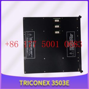
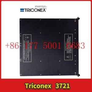
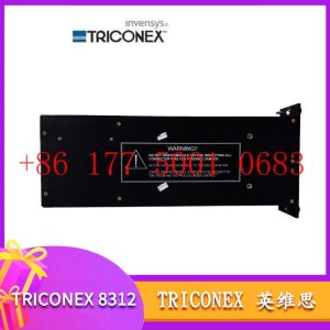
4000056-006N TRICONEX nput/output communication card
4000056-006N TRICONEX nput/output communication card
Module Clips Drive controller servo motor
Contact: Mr. Lai
Wechat:17750010683
Whats app:+86 17750010683
Skype:+86 17750010683
QQ: 3221366881
3221366881@qq.com
Application of IO Link in Industrial Automation
This article mainly introduces the overall solution of ST IO Link communication master station used in industrial systems, including the following 5 aspects:
Firstly, the application of IO Link in industrial automation; The second is the introduction of ST IO Link main station transceiver; The third is the introduction of our ST”s IO Link main site evaluation board; The fourth is an introduction to the reference design scheme of the IO Link main station; The fifth is a demonstration of the IO Link master station reference design.
The industrial automation system can be said to be composed of many levels. The top level is usually industrial Ethernet to transmit data to the upper control center or monitoring center of the factory, while the middle layer is usually some PLC system for specialized process processing, such as controlling a specialized assembly line or production line. At the bottom, there are usually many industrial sensors, such as temperature sensors, pressure sensors, flow sensors, or proximity sensors, as well as some actuators, such as valves, moving lights, relays, or contactors, which are used for collecting and controlling physical quantities.
Between these levels, there will also be some modules or gateways for conversion and processing work. Therefore, in traditional industrial systems, there are many different level standards and communication protocols on site, resulting in poor modularity and versatility. Because there are both analog signals on site, such as a 4 to 20 mA current loop and analog voltage signals, as well as digital signals. In such an environment, analog signals are particularly susceptible to interference from harsh on-site environments. At the same time, sensors or actuators for analog transmission cannot perform on-site remote configuration or calibration 4000056-006N TRICONEX nput/output communication card diagnosis work. In order to solve the transmission of the last segment of data to sensors and actuators in industrial field environments, as described earlier, we have introduced a specialized digital interface IO Link to achieve fully digital transmission between the interface modules of sensors and industrial field buses. The bidirectional data transmission makes it possible to parameterize the interaction of on-site data, diagnose and transmit information. By using this technology, remote condition monitoring and predictable maintenance of terminal equipment can be achieved, thereby effectively alleviating the problem of production line downtime.
Its advantages include:4000056-006N TRICONEX nput/output communication card
Firstly, whether it is a pure digital sensor, an analog sensor after digital quantization, or different types of actuators, unified access can be achieved, thus achieving a simplified and standardized system architecture. Secondly, the transmission of digital signals will have stronger anti-interference ability than the transmission of analog signals, so the reliability of the system will also be stronger. Thirdly, through the bidirectional transmission of digital signals, more intelligent and advanced actuators or sensors can be used, making it easier to achieve status monitoring and system diagnostic protection functions. In this way, any issues and status of the production line can be monitored and maintained in real-time, ensuring the reliability, maintainability, and upgradability of the entire production line, thereby ensuring the minimum downtime.
The following is the specific content about IO Link technology
Firstly, the definition of the IO LINK standard enables data transmission, processing, configuration, and diagnostic information exchange between sensors or actuators and control systems. Secondly, this is a simple peer-to-peer communication architecture, where a master port is connected to a device port. Then, it can achieve compatibility with existing communication architectures, such as reusing cables and interfaces. At the same time, the IO Link system also has backward compatibility upgrade capability, as the master end of the system uses digital binary serial communication to interact with devices, and vice versa.
It can be said that IO link makes the system simpler:
Firstly, this is a universal standard communication method that complies with IEC61131-9. Secondly, IO Link is an intelligent communication system that solves the digital information exchange and transmission of the last distance from the control host to the terminal device. Thirdly, IO Link is simple to use and can be said to be plug and play, compatible with some existing system devices.
Some related products and solutions provided by ST in IO Link communication solutions
Firstly, in this communication system, the IO Link Master, which connects to the upper computer controller, is one of the main key solutions that will be mentioned later. Secondly, ST can provide some communication chips on the IO Link Master project, such as L6360. On the other side of the sensor or actuator end, namely the IO Link Slave end, ST can provide communication chips L6362A and L6364 on this IO Link Slave slave project. According to standards, this three-wire point-to-point communication method is easily compatible with some existing sensor actuators” standard ports, such as M12 standard industrial connectors and M12 standard connector wires. In addition, its advantages include the ability to achieve point-to-point bidirectional signal transmission within a single cable, as well as the general power supply requirements of the master end to the sensor actuator. According to the general requirements of the current industry, the maximum length of this cable is 20 meters, and the three wires inside are 24V, 0V, and data cables. The L+of this chip can support up to 500 milliamperes. If greater current is needed, there are also other L+drivers, including Load Switch IPS and other products, which can provide greater current or can be applied externally. The IO Link communication speed can generally reach a baud rate of 230.4K per COM3, and it also has functions such as status indication and detection.
For some specific application characteristics of IO Link, the communication transceiver system composed of L6360 and L6362A can support three standard data types of IO Link, namely COM1 (4.8k), COM2 (38.4K), and COM3 (230.4K) modes. This communication system can meet the requirements of all modern standards, industrial sensors, and actuators: firstly, it can quickly and very easily configure or reconfigure sensors or actuators. Secondly, it can be widely applied to various standardized sensors or systems that execute information. Thirdly, as a digital communication system, compared to traditional analog signal transmission systems, it can reduce power consumption and improve system efficiency. Fourthly, it has complete diagnostic and protection functions, which can improve the reliability of related systems. Therefore, it can be widely used to drive various digital sensors and actuators, as well as input and output modules of PLC, in order to achieve and meet various requirements of Industry 4.0.
How to Determine the Interference Problem of PROFINET IO Communication
Preliminary Diagnosis of PROFINET Interference Problems
1. Overview
When debugging PROFINET IO communication, it is common to encounter communication failures. One of the reasons for communication failures is interference. PROFINET IO communication equipment often operates in complex industrial electromagnetic environments, and incorrect shielding grounding or non-standard installation may lead to communication interference problems. Since optical signals are not affected by electromagnetic interference, this article only introduces interference problems with electrical signals.
2. How to determine interference issues
If PROFINET IO communication is affected by electromagnetic interference, a simple judgment can generally be made through the following aspects:
2.1. Judging the communication status through PROFINET IO
If the following communication phenomena are found during PROFINET IO communication debugging or operation, it may be affected by electromagnetic interference:
① Occasionally, communication is interrupted and restored.
② When certain on-site devices or specific operations are turned on, communication is interrupted, and on the contrary, communication returns to normal.
2.2. By using STEP7 online diagnostic information to determine and view the diagnostic buffer information of the IO controller, how to detect the presence of frequent communication failures and recovery information between the IO controller and IO devices in the diagnostic buffer, as shown in the following figure, may be affected by electromagnetic interference:
14 STEP7 Device Diagnostic Buffer Information
3. How to troubleshoot and solve interference problems
If a suspected electromagnetic interference causing PROFINET IO communication failure is found, how should we troubleshoot and solve it? The following will be introduced from the following aspects:
3.1 Increase PROFINET IO communication watchdog time
Due to PROFINET IO communication failure occurring during watchdog time, the IO controller did not provide input or output data (IO data) to the IO device, and watchdog time=the number of update cycles allowed for IO data loss × The refresh time is usually automatically calculated and allocated by the IO controller. This time value is generally small. If electromagnetic interference is encountered, the probability of communication failure occurring within the automatically calculated watchdog time will increase. At this time, we can appropriately increase the PROFINET IO communication refresh time or the number of update cycles allowed for IO data loss to increase the watchdog time. However, this method may not solve serious electromagnetic interference problems, and it is recommended to eliminate and solve them through subsequent methods.
What is the difference between remote IO and distributed IO
People often discuss the difference between remote IO and distributed IO. However, some people believe that they are the same and terms can be exchanged, while others believe the opposite. What is the difference between remote I/O and distributed I/O? The following is a guide from remote IO manufacturer Zhongshan Technology to understand the difference between remote IO and distributed IO.
Remote and distributed within the location range.4000056-006N TRICONEX nput/output communication card
Today”s DCS is a control system with many distributed autonomous controllers, each with many continuous operations. This controller is bundled together by a central monitoring controller. We have used the terms remote and distributed in the locations of I/O and controllers. It is easy to see how these terms are misunderstood.
From the perspective of PLC, remote I/O represents the actual distance that the I/O module is away from the control PLC. Distributed I/O is very intelligent, as mentioned earlier, remote I/O is sometimes referred to as distributed I/O. Let”s take a look at the definition of distributed I/O. This definition is different from remote I/O.
Generally speaking, distributed I/O has a brain or some computing power. By default, it is remote. As mentioned earlier, remote I/O is located physically far from the control PLC. Remote I/O has no brain and cannot perform any computational functions at all. It can be said with certainty that when you hear the term remote I/O, it only involves one controller or PLC, while distributed I/O has multiple controllers.
ZSR-Ethernet-2184 is a distributed Ethernet RTU that supports 4-way switch digital input (Di), 8-way analog input (Ai), 4-way relay (Do) output, 1-way RS485 serial port data acquisition to Ethernet, and Modbus RTU terminal. Merge 485 to Ethernet serial port server function, support Modbus to TCP/UDP protocol conversion, support virtual serial port, and interface with various configuration software. Supports signal acquisition in the range of 0-5V, 0-10V, 0-30V, or 0-20ma, 4-20ma, with built-in software and hardware watchdog, industrial grade components, and stable operation in an industrial environment of -40~85 ° C.
Building a High Channel Density Digital IO Module for the Next Generation Industrial Automation Controller
There are currently many articles introducing Industry 4.0, and smart sensors are becoming increasingly popular in factory environments (I and other authors have written about these topics). Although we have all noticed a significant increase in the use of sensors in factories, processing plants, and even some newly built automation systems, the widespread use of sensors has also brought about an important change, which is the need to handle a large amount of IO within these old controllers. These IOs may be digital or analog. This requires the construction of high-density IO modules with size and heat limitations.
Usually, digital IO in PLC consists of discrete devices such as resistors/capacitors or independent FET drives. In order to minimize the size of the controller as much as possible and to handle 2 to 4 times the number of channels, this has led to a shift from a separate approach to an integrated approach.4000056-006N TRICONEX nput/output communication card
We can use the entire article to illustrate the drawbacks of the split method, especially when the number of channels processed by each module reaches 8 or more. However, when it comes to high heat/power consumption, a large number of split components (from the perspective of size and mean time between failures (MTBF)), and the need for reliable system specifications, it is sufficient to demonstrate that the split method is not feasible.
Figure 1 shows the technical challenges faced in building high-density digital input (DI) and digital output (DO) modules. In both DI and DO systems, size and heat dissipation issues need to be considered.
Design a High Channel Density Digital Input Module
The traditional split design uses a resistive voltage divider network to convert 24V/48V signals into signals that can be used by microcontrollers. The front-end can also use discrete RC filters. If isolation is required, external optocouplers are sometimes used
For example, the current limiting value of DI devices in ADI is 3.5mA/channel. So, as shown in the figure, we use two channels in parallel. If the system must be connected to a Type 2 input, adjust the REFDI resistance and RIN resistance. For some newer components, we can also use pins or select current values through software.
To support a 48V digital input signal (not a common requirement), a similar process needs to be used, and an external resistor must be added to adjust the voltage threshold at one end of the field. Set the value of this external resistor so that the current limiting value * R+threshold of the pin meets the voltage threshold specification at one end of the field (see device data manual).
Finally, due to the connection between the digital input module and the sensor, the design must meet the requirements of reliable operating characteristics. When using a split type scheme, these protective functions must be carefully designed. When selecting integrated digital input devices, ensure that the following are determined according to industry standards:
Wide input voltage range (e.g. up to 40V).
Able to use on-site power supply (7V to 65V).
Capable of withstanding high ESD (± 15kV ESD air gap) and surges (usually 1KV).
Providing overvoltage and overheating diagnosis is also very useful for MCU to take appropriate actions.
Design a High Channel Density Digital Output Module
A typical discrete digital output design has a FET with a driving circuit driven by a microcontroller. Different methods can be used to configure FETs to drive microcontrollers.
The definition of a high-end load switch is that it is controlled by an external enable signal and connects or disconnects the power supply from a given load. Compared to low-end load switches, high-end switches provide current to the load, while low-end switches connect or disconnect the grounding connection of the load to obtain current from the load. Although they all use a single FET, the problem with low-end switches is that there may be a short circuit between the load and ground. High end switches protect the load and prevent short circuits to ground. However, the implementation cost of low-end switches is lower. Sometimes, the output driver is also configured as a push-pull switch, requiring two MOSFETs. Refer to Figure 4 below.
Integrated DO devices can integrate multiple DO channels into a single device. Due to the different FET configurations used for high-end, low-end, and push-pull switches, different devices can be used to achieve each type of output driver.
1.Has been engaged in industrial control industry for a long time, with a large number of inventories.
2.Industry leading, price advantage, quality assurance
3.Diversified models and products, and all kinds of rare and discontinued products
4.15 days free replacement for quality problems
ABB — AC 800M controller, Bailey, PM866 controller, IGCT silicon controlled 5SHY 3BHB01 3BHE00 3HNA00 DSQC series
BENTLY — 3500 system/proximitor, front and rear card, sensor, probe, cable 3500/20 3500/61 3500/05-01-02-00-001 3500/40M 176449-01 3500/22M 138607-01
Emerson — modbus card, power panel, controller, power supply, base, power module, switch 1C31,5X00, CE400, A6500-UM, SE3008,1B300,1X00,
EPRO — PR6423 PR6424 PR6425 PR6426 PR9376 PR9268 Data acquisition module, probe, speed sensor, vibration sensor
FOXBORO — FCP270 FCP280 FCM10EF FBM207 P0914TD CP40B FBI10E FBM02 FBM202 FBM207B P0400HE Thermal resistance input/output module, power module, communication module, cable, controller, switch
GE —- IS200/215/220/230/420 DS200/215 IC693/695/697/698 VMICPCI VMIVME 369-HI-R-M-0-0-E 469 module, air switch, I/O module, display, CPU module, power module, converter, CPU board, Ethernet module, integrated protection device, power module, gas turbine card
HIMA — F3 AIO 8/4 01 F3231 F8627X Z7116 F8621A 984862160 F3236 F6217 F7553 DI module, processor module, AI card, pulse encoder
Honeywell — Secure digital output card, program module, analog input card, CPU module, FIM card
MOOG — D136-001-007 Servo valve, controller, module
NI — SCXI-1100 PCI – PXIE – PCIE – SBRIO – CFP-AO-210 USB-6525 Information Acquisition Card, PXI Module, Card
Westinghouse — RTD thermal resistance input module, AI/AO/DI/DO module, power module, control module, base module
Woodward — 9907-164 5466-258 8200-1300 9907-149 9907-838 EASYGEN-3500-5/P2 8440-2145 Regulator, module, controller, governor
YOKOGAWA – Servo module, control cabinet node unit
Main products:
PLC, DCS, CPU module, communication module, input/output module (AI/AO/DI/DO), power module, silicon controlled module, terminal module, PXI module, servo drive, servo motor, industrial display screen, industrial keyboard, controller, encoder, regulator, sensor, I/O board, counting board, optical fiber interface board, acquisition card, gas turbine card, FIM card and other automatic spare parts