")
Description
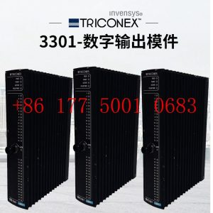
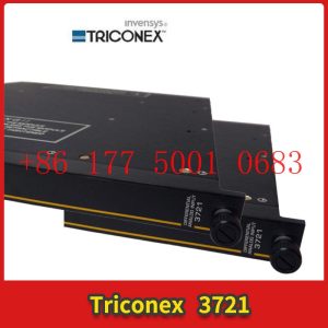
4000056-006N TRICONEX controller
4000056-006N TRICONEX controller
Module Clips Drive controller servo motor
Contact: Mr. Lai
Wechat:17750010683
Whats app:+86 17750010683
Skype:+86 17750010683
QQ: 3221366881
3221366881@qq.com
What is the difference between remote IO and distributed IO
People often discuss the difference between remote IO and distributed IO. However, some people believe that they are the same and terms can be exchanged, while others believe the opposite. What is the difference between remote I/O and distributed I/O? The following is a guide from remote IO manufacturer Zhongshan Technology to understand the difference between remote IO and distributed IO.
Remote and distributed within the location range.4000056-006N TRICONEX controller
Today”s DCS is a control system with many distributed autonomous controllers, each with many continuous operations. This controller is bundled together by a central monitoring controller. We have used the terms remote and distributed in the locations of I/O and controllers. It is easy to see how these terms are misunderstood.
From the perspective of PLC, remote I/O represents the actual distance that the I/O module is away from the control PLC. Distributed I/O is very intelligent, as mentioned earlier, remote I/O is sometimes referred to as distributed I/O. Let”s take a look at the definition of distributed I/O. This definition is different from remote I/O.
Generally speaking, distributed I/O has a brain or some computing power. By default, it is remote. As mentioned earlier, remote I/O is located physically far from the control PLC. Remote I/O has no brain and cannot perform any computational functions at all. It can be said with certainty that when you hear the term remote I/O, it only involves one controller or PLC, while distributed I/O has multiple controllers.
ZSR-Ethernet-2184 is a distributed Ethernet RTU that supports 4-way switch digital input (Di), 8-way analog input (Ai), 4-way relay (Do) output, 1-way RS485 serial port data acquisition to Ethernet, and Modbus RTU terminal. Merge 485 to Ethernet serial port server function, support Modbus to TCP/UDP protocol conversion, support virtual serial port, and interface with various configuration software. Supports signal acquisition in the range of 0-5V, 0-10V, 0-30V, or 0-20ma, 4-20ma, with built-in software and hardware watchdog, industrial grade components, and stable operation in an industrial environment of -40~85 ° C.
Building a High Channel Density Digital IO Module for the Next Generation Industrial Automation Controller
There are currently many articles introducing Industry 4.0, and smart sensors are becoming increasingly popular in factory environments (I and other authors have written about these topics). Although we have all noticed a significant increase in the use of sensors in factories, processing plants, and even some newly built automation systems, the widespread use of sensors has also brought about an important change, which is the need to handle a large amount of IO within these old controllers. These IOs may be digital or analog. This requires the construction of high-density IO modules with size and heat limitations.
Usually, digital IO in PLC consists of discrete devices such as resistors/capacitors or independent FET drives. In order to minimize the size of the controller as much as possible and to handle 2 to 4 times the number of channels, this has led to a shift from a separate approach to an integrated approach.4000056-006N TRICONEX controller
We can use the entire article to illustrate the drawbacks of the split method, especially when the number of channels processed by each module reaches 8 or more. However, when it comes to high heat/power consumption, a large number of split components (from the perspective of size and mean time between failures (MTBF)), and the need for reliable system specifications, it is sufficient to demonstrate that the split method is not feasible.
Figure 1 shows the technical challenges faced in building high-density digital input (DI) and digital output (DO) modules. In both DI and DO systems, size and heat dissipation issues need to be considered.
Design a High Channel Density Digital Input Module
The traditional split design uses a resistive voltage divider network to convert 24V/48V signals into signals that can be used by microcontrollers. The front-end can also use discrete RC filters. If isolation is required, external optocouplers are sometimes used
For example, the current limiting value of DI devices in ADI is 3.5mA/channel. So, as shown in the figure, we use two channels in parallel. If the system must be connected to a Type 2 input, adjust the REFDI resistance and RIN resistance. For some newer components, we can also use pins or select current values through software.
To support a 48V digital input signal (not a common requirement), a similar process needs to be used, and an external resistor must be added to adjust the voltage threshold at one end of the field. Set the value of this external resistor so that the current limiting value * R+threshold of the pin meets the voltage threshold specification at one end of the field (see device data manual).
Finally, due to the connection between the digital input module and the sensor, the design must meet the requirements of reliable operating characteristics. When using a split type scheme, these protective functions must be carefully designed. When selecting integrated digital input devices, ensure that the following are determined according to industry standards:
Wide input voltage range (e.g. up to 40V).
Able to use on-site power supply (7V to 65V).
Capable of withstanding high ESD (± 15kV ESD air gap) and surges (usually 1KV).
Providing overvoltage and overheating diagnosis is also very useful for MCU to take appropriate actions.
Design a High Channel Density Digital Output Module
A typical discrete digital output design has a FET with a driving circuit driven by a microcontroller. Different methods can be used to configure FETs to drive microcontrollers.
The definition of a high-end load switch is that it is controlled by an external enable signal and connects or disconnects the power supply from a given load. Compared to low-end load switches, high-end switches provide current to the load, while low-end switches connect or disconnect the grounding connection of the load to obtain current from the load. Although they all use a single FET, the problem with low-end switches is that there may be a short circuit between the load and ground. High end switches protect the load and prevent short circuits to ground. However, the implementation cost of low-end switches is lower. Sometimes, the output driver is also configured as a push-pull switch, requiring two MOSFETs. Refer to Figure 4 below.
Integrated DO devices can integrate multiple DO channels into a single device. Due to the different FET configurations used for high-end, low-end, and push-pull switches, different devices can be used to achieve each type of output driver.
How to Build High Channel Density Digital IO Modules for the Next Generation Industrial Automation Controllers
With the rapid development of industrial automation, digital IO modules have become an indispensable part of industrial automation controllers. The digital IO module can connect the controller with external devices, such as sensors, actuators, etc., to achieve monitoring and control of industrial production processes. However, with the continuous development of industrial automation, digital IO modules need to have higher channel density and stronger functionality to meet the needs of new industrial automation controllers. Therefore, it is very important to build high channel density digital IO modules for the next generation of industrial automation controllers.
The digital IO module is one of the most fundamental modules in industrial automation controllers, and its main function is to connect the controller with external devices to achieve signal input and output. The digital IO module usually includes two parts: a digital input module and a digital output module. The digital input module can convert the digital signals of external devices into signals that the controller can read, while the digital output module can convert the digital signals output by the controller into signals that external devices can read. The channel density of a digital IO module refers to the number of digital input or digital output channels provided on the module, which is the input and output capacity of the module.
With the development of industrial automation, digital IO modules need to have higher channel density and stronger functions to meet the needs of new industrial automation controllers. The following are several aspects to consider when building a high channel density digital IO module for the next generation of industrial automation controllers:4000056-006N TRICONEX controller
1. Choose the appropriate communication protocol
Digital IO modules typically communicate with controllers through communication protocols, so choosing a suitable communication protocol is crucial. Common communication protocols include Modbus, Profibus, CANopen, Ethernet, etc. Different communication protocols have different advantages and disadvantages, and selecting a suitable communication protocol requires considering the following factors:
(1) Communication speed: The faster the communication speed, the shorter the response time of the digital IO module, which can process input and output signals faster.
(2) Communication distance: The farther the communication distance, the wider the application range of digital IO modules.
(3) Reliability: The reliability of communication protocols determines the stability and reliability of digital IO modules.
(4) Cost: Different communication protocols have different costs, and suitable communication protocols need to be selected based on actual needs.
2. Choose the appropriate digital IO chip
The digital IO chip is the core component of the digital IO module, and its performance and function directly affect the channel density and function of the digital IO module. Choosing a suitable digital IO chip requires considering the following factors:
(1) Channel density: The channel density of digital IO chips determines the channel density of digital IO modules, and channel density needs to be selected based on actual needs.
(2) Input/output type: Digital IO chips usually support digital input and digital output, and some chips also support functions such as analog input and output, counters, etc.
(3) Speed: The speed of the digital IO chip determines the response speed of the digital IO module, and it is necessary to choose a chip with a faster speed.
(4) Accuracy: The accuracy of digital IO chips determines the signal accuracy of digital IO modules, and it is necessary to choose chips with higher accuracy.
(5) Cost: Different digital IO chips have different costs, and suitable chips need to be selected based on actual needs.
3. Optimize circuit design
The circuit design of digital IO modules has a significant impact on their performance and stability. In order to improve the channel density and functionality of digital IO modules, it is necessary to optimize circuit design, such as:
(1) Using high-speed digital IO chips: Using high-speed digital IO chips can improve the response speed and accuracy of the module.
(2) Adopting anti-interference design: In order to improve the stability of the digital IO module, it is necessary to adopt anti-interference design, such as using filters, isolators, etc.
(3) Using optimized PCB layout: Optimizing PCB layout can reduce noise and interference in digital IO modules, improve module performance and stability.
4. Choose the appropriate shell material and size
Digital IO modules typically need to be installed in cabinets or control cabinets, so choosing the appropriate housing material and size is crucial. The shell material should have good protective and heat dissipation properties to protect the circuits of the digital IO module from external environmental influences. The shell size should be able to adapt to different installation environments, such as cabinets, control cabinets, etc.
5. Optimize software design
The software design of the digital IO module determines its functionality and performance. In order to achieve high channel density and stronger functionality, it is necessary to optimize software design, such as:
(1) Supporting multiple input and output types: Supporting multiple input and output types can meet different application needs, such as digital input and output, analog input and output, counters, etc.
(2) Supporting multiple communication protocols: Supporting multiple communication protocols can adapt to different controllers and application environments.
(3) Support for online debugging and monitoring: Supporting online debugging and monitoring can facilitate user diagnosis and maintenance of modules.
(4) Support for expansion function: Supporting expansion function can increase the functionality and application range of the module while ensuring channel density.
In summary, building a high channel density digital IO module for the next generation of industrial automation controllers requires multiple considerations, including selecting suitable communication protocols, selecting suitable digital IO chips, optimizing circuit design, selecting suitable shell materials and sizes, and optimizing software design. Only by comprehensively considering these factors can a digital IO module with high channel density and stronger functionality be constructed to meet the needs of new industrial automation controllers.
How to assign IO devices to IO controllers?
PROFINET IO system
The PROFINET IO system consists of a PROFINET IO controller and its assigned PROFINET IO devices. After adding IO controllers and IO devices, it is necessary to assign IO controllers to the IO devices to form a basic PROFINET IO system.
Prerequisite requirements
● Already in the network view of STEP 7.
A CPU has been placed (e.g. CPU 1516-3 PN/DP).
● An IO device has been placed (e.g. IM 155-6 PN ST)
Operating Steps (Method 1)
To assign IO devices to IO controllers, follow these steps:
1. Move the mouse pointer over the interface of the IO device.
2. Hold down the left mouse button.
3. Drag the mouse pointer.
The pointer will now use the networking symbol to indicate the “networking” mode. At the same time, you can see a lock character appearing on the pointer
Number. The lock symbol only disappears when the pointer moves to a valid target position.
4. Now, move the pointer to the interface of the desired IO controller and release the left mouse button.
5. Now assign the IO device to the IO controller.
Operating Steps (Method 2)
To assign IO devices to IO controllers, follow these steps:
1. Move the mouse pointer over the word “Unassigned” in the bottom left corner of the IO device icon.
2. Click the left mouse button.
3. Select the IO controller interface to be connected from the available interfaces that appear.
4. Now assign the IO device to the IO controller.
1.Has been engaged in industrial control industry for a long time, with a large number of inventories.
2.Industry leading, price advantage, quality assurance
3.Diversified models and products, and all kinds of rare and discontinued products
4.15 days free replacement for quality problems
ABB — AC 800M controller, Bailey, PM866 controller, IGCT silicon controlled 5SHY 3BHB01 3BHE00 3HNA00 DSQC series
BENTLY — 3500 system/proximitor, front and rear card, sensor, probe, cable 3500/20 3500/61 3500/05-01-02-00-001 3500/40M 176449-01 3500/22M 138607-01
Emerson — modbus card, power panel, controller, power supply, base, power module, switch 1C31,5X00, CE400, A6500-UM, SE3008,1B300,1X00,
EPRO — PR6423 PR6424 PR6425 PR6426 PR9376 PR9268 Data acquisition module, probe, speed sensor, vibration sensor
FOXBORO — FCP270 FCP280 FCM10EF FBM207 P0914TD CP40B FBI10E FBM02 FBM202 FBM207B P0400HE Thermal resistance input/output module, power module, communication module, cable, controller, switch
GE —- IS200/215/220/230/420 DS200/215 IC693/695/697/698 VMICPCI VMIVME 369-HI-R-M-0-0-E 469 module, air switch, I/O module, display, CPU module, power module, converter, CPU board, Ethernet module, integrated protection device, power module, gas turbine card
HIMA — F3 AIO 8/4 01 F3231 F8627X Z7116 F8621A 984862160 F3236 F6217 F7553 DI module, processor module, AI card, pulse encoder
Honeywell — Secure digital output card, program module, analog input card, CPU module, FIM card
MOOG — D136-001-007 Servo valve, controller, module
NI — SCXI-1100 PCI – PXIE – PCIE – SBRIO – CFP-AO-210 USB-6525 Information Acquisition Card, PXI Module, Card
Westinghouse — RTD thermal resistance input module, AI/AO/DI/DO module, power module, control module, base module
Woodward — 9907-164 5466-258 8200-1300 9907-149 9907-838 EASYGEN-3500-5/P2 8440-2145 Regulator, module, controller, governor
YOKOGAWA – Servo module, control cabinet node unit
Main products:
PLC, DCS, CPU module, communication module, input/output module (AI/AO/DI/DO), power module, silicon controlled module, terminal module, PXI module, servo drive, servo motor, industrial display screen, industrial keyboard, controller, encoder, regulator, sensor, I/O board, counting board, optical fiber interface board, acquisition card, gas turbine card, FIM card and other automatic spare parts