")
Description
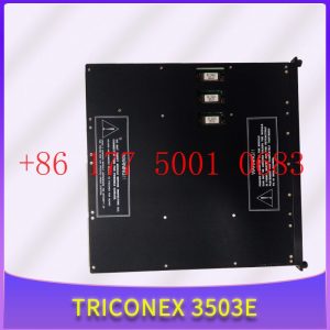
3601E TRICONEX controller
3601E TRICONEX controller
Module Clips Drive controller servo motor
Contact: Mr. Lai
Wechat:17750010683
Whats app:+86 17750010683
Skype:+86 17750010683
QQ: 3221366881
3221366881@qq.com
Application Scheme of Industrial Ethernet Remote IO Module in Intelligent Manufacturing Workshop
With the advent of Industry 4.0, intelligent manufacturing has become a trend in industrial production. Intelligent manufacturing requires efficient, stable, and reliable industrial Ethernet remote IO modules to monitor the production process. This article will share an application case of an intelligent manufacturing workshop based on industrial Ethernet remote IO module.3601E TRICONEX controller
The production process of this intelligent manufacturing workshop is mainly divided into two parts: injection molding and automated assembly. The injection molding process requires controlling parameters such as the melting temperature of the melt, the speed and pressure of the injection molding machine. The automated assembly process requires controlling the actions of the assembly robot and detecting the quality of the product. In addition to these production process data, there are also equipment production data such as daily and weekly production in the workshop, as well as equipment status data such as operation, manual, automatic, mold adjustment, and alarm.
In the past, the production process of the factory mainly relied on traditional hard wiring to control the production process, resulting in low work efficiency due to the need for frequent replacement of transmission lines to meet production needs. Moreover, it is very difficult to collect a large number of types of detection and monitoring data for intelligent manufacturing. In order to improve efficiency, production quality, and reliability, the factory has introduced the industrial Ethernet remote IO module MxxT using barium rhenium technology.
The injection molding machine itself comes with MODBUS industrial control bus data or basic status signal output. The barium rhenium technology remote IO module collects data from the device interface RS232/RS485 port, collects status information of the injection molding machine such as startup, operation, and pause, and uploads it to the injection molding machine controller, or wirelessly uploads it to the cloud server. Based on devices, according to the communication protocols and interfaces of different devices, data is obtained by calling their interface channels, and then transmitted to the server.
The remote IO module is connected to the controller of the injection molding machine, and the operation data of the injection molding machine is uploaded and distributed wirelessly, achieving remote monitoring and intelligent control of the injection molding machine. In addition, the remote I/O module supports perceptual access to peripheral devices such as mold temperature machines, cutting machines, and dryers for injection molding machines, providing users with smart factory services.
During the injection molding process, the industrial Ethernet remote IO module transmits real-time data such as temperature, pressure, and speed to the main controller for monitoring and adjustment, ensuring the stability and compliance of production parameters under different conditions. In the automated assembly process, the industrial Ethernet remote IO module collects data through sensors and other devices, and transmits the relevant data to the main controller for adjustment of relevant actions. For example, the industrial Ethernet remote IO module can monitor the actions of assembly robots, detect the accuracy of product assembly and product quality, and ensure the production quality and stability of the product. At the same time, all production data can also be collected and analyzed remotely, helping enterprise managers better monitor production efficiency and quality.
By introducing industrial Ethernet remote IO modules, this intelligent manufacturing workshop not only improves production efficiency and stability, but also reduces labor and energy costs. Because the industrial Ethernet remote IO module can help enterprises complete the collection and monitoring of production data with one click, as well as avoid unnecessary line replacement and the need for workers to enter and exit the production process, thereby reducing costs and improving production efficiency for enterprises.
In summary, the application of industrial Ethernet remote IO modules in intelligent manufacturing workshops not only improves production efficiency and quality, reduces costs, but also achieves intelligent and digital management of production processes, bringing more opportunities and development space for enterprise development.3601E TRICONEX controller
In addition, this device is widely used for networking and data collection of industrial equipment such as injection molding machines, air compressors, CNC machine tools, on-site PLCs, instruments, sensors, CNC, and electromechanical equipment.
Building a High Channel Density Digital IO Module for the Next Generation Industrial Automation Controller
There are currently many articles introducing Industry 4.0, and smart sensors are becoming increasingly popular in factory environments (I and other authors have written about these topics). Although we have all noticed a significant increase in the use of sensors in factories, processing plants, and even some newly built automation systems, the widespread use of sensors has also brought about an important change, which is the need to handle a large amount of IO within these old controllers. These IOs may be digital or analog. This requires the construction of high-density IO modules with size and heat limitations. In this article, I will focus on digital IO, and in subsequent articles, I will introduce analog IO.
Usually, digital IO in PLC consists of discrete devices such as resistors/capacitors or independent FET drives. In order to minimize the size of the controller as much as possible and to handle 2 to 4 times the number of channels, this has led to a shift from a separate approach to an integrated approach.
We can use the entire article to illustrate the drawbacks of the split method, especially when the number of channels processed by each module reaches 8 or more. However, when it comes to high heat/power consumption, a large number of split components (from the perspective of size and mean time between failures (MTBF)), and the need for reliable system specifications, it is sufficient to demonstrate that the split method is not feasible.
Figure 1 shows the technical challenges faced in building high-density digital input (DI) and digital output (DO) modules. In both Di and DO systems, size and heat dissipation issues need to be considered.
Digital input
size
heat
Supports all input types
Type 1, 2, 3, Input
Supports 24 V and 48 V inputs
Robust operating specifications
Wire breakage detection
Digital output
Support for different types of output driver configurations
size
Integrated demagnetization of inductive loads
Heat – When driving multiple outputs
Drive accuracy
diagnosis
For digital input, it is also important to note that it supports different input types, including 1/2/3 type inputs, and in some cases, 24V and 48V inputs. In all cases, reliable operating characteristics are crucial, and sometimes circuit detection is also crucial.
For digital outputs, the system uses different FET configurations to drive the load. The accuracy of the driving current is usually an important consideration. In many cases, diagnosis is also very important.
We will explore how integrated solutions can help address some of these challenges.
Design a High Channel Density Digital Input Module
The traditional split design uses a resistive voltage divider network to convert 24V/48V signals into signals that can be used by microcontrollers. The front-end can also use discrete RC filters. If isolation is required, external optocouplers are sometimes used.
Figure 1 shows a typical discrete method for constructing digital input circuits.
Figure 1. Considerations for digital input and output modules.
This type of design is suitable for a certain number of digital inputs; 4 to 8 per board. Beyond this number, this design will soon become impractical. This separation scheme can bring various problems, including:
High power consumption and related board high temperature points.
Each channel requires an optocoupler.
Excessive components can lead to low FIT rate and even require larger devices.
More importantly, the split design method means that the input current increases linearly with the input voltage. Assuming a 2.2K Ω input resistor and 24V V is used. When the input is 1, for example, at 24V, the input current is 11mA, which is equivalent to a power consumption of 264mW. The power consumption of the 8-channel module is greater than 2W, and the power consumption of the 32-bit module is greater than 8W. Refer to Figure 3 below
From a cooling perspective alone, this split design cannot support multiple channels on a single board.
One of the biggest advantages of integrated digital input design is the significant reduction in power consumption, thereby reducing heat dissipation. Most integrated digital input devices allow configurable input current limitations to significantly reduce power consumption.
When the current limiting value is set to 2.6mA, the power consumption is significantly reduced, with each channel approximately 60mW. The rated value of the 8-channel digital input module can now be set below 0.5
Another reason for opposing the use of split logic design is that sometimes DI modules must support different types of inputs. The standard 24V digital input specifications published by IEC are divided into Type 1, Type 2, and Type 3. Type 1 and Type 3 are usually used in combination because their current and threshold limits are very similar. Type 2 has a current limit of 6mA, which is higher. When using the split method, it may be necessary to redesign as most discrete values need to be updated.
However, integrated digital input products typically support all three types. Essentially, Type 1 and Type 3 are generally supported by integrated digital input devices. However, in order to meet the minimum current requirement of 6mA for Type 2 input, we need to use two channels in parallel for one field input. And only adjust the current limiting resistance. This requires a circuit board change, but the change is minimal.
For example, the current maximum integrated (now part of ADI company) DI device has a current limiting value of 3.5mA/channel. So, as shown in the figure, we use two channels in parallel. If the system must be connected to a Type 2 input, adjust the REFDI resistance and RIN resistance. For some newer components, we can also use pins or select current values through software.
To support a 48V digital input signal (not a common requirement), a similar process needs to be used, and an external resistor must be added to adjust the voltage threshold at one end of the field. Set the value of this external resistor so that the current limiting value * R+threshold of the pin meets the voltage threshold specification at one end of the field (see device data manual).
Finally, due to the connection between the digital input module and the sensor, the design must meet the requirements of reliable operating characteristics. When using a split type scheme, these protective functions must be carefully designed. When selecting integrated digital input devices, ensure that the following are determined according to industry standards:
Wide input voltage range (e.g. up to 40V).
Able to use on-site power supply (7V to 65V).
Capable of withstanding high ESD (± 15kV ESD air gap) and surges (usually 1KV).
Providing overvoltage and overheating diagnosis is also very useful for MCU to take appropriate actions.
Design a High Channel Density Digital Output Module
A typical discrete digital output design has a FET with a driving circuit driven by a microcontroller. Different methods can be used to configure FETs to drive microcontrollers.
The definition of a high-end load switch is that it is controlled by an external enable signal and connects or disconnects the power supply from a given load. Compared to low-end load switches, high-end switches provide current to the load, while low-end switches connect or disconnect the grounding connection of the load to obtain current from the load. Although they all use a single FET, the problem with low-end switches is that there may be a short circuit between the load and ground. High end switches protect the load and prevent short circuits to ground. However, the implementation cost of low-end switches is lower. Sometimes, the output driver is also configured as a push-pull switch, requiring two MOSFETs. Refer to Figure 6 below:
Integrated DO devices can integrate multiple DO channels into a single device. Due to the different FET configurations used for high-end, low-end, and push-pull switches, different devices can be used to achieve each type of output driver.
Estimated power consumption of digital input modules constructed using split logic.
Internal demagnetization of inductive loads
One of the key advantages of integrated digital output devices is their built-in inductive load demagnetization function.
Inductive load is any device containing a coil that, after being energized, typically performs some mechanical work, such as solenoid valves, motors, and actuators. The magnetic field caused by current can move the switch contacts in relays or contactors to operate solenoid valves or rotate the motor shaft. In most cases, engineers use high-end switches to control inductive loads, and the challenge is how to discharge the inductance when the switch is turned on and the current no longer flows into the load. The negative effects caused by improper discharge include: possible arcing of relay contacts, significant negative voltage spikes that damage sensitive ICs, and the generation of high-frequency noise or EMI, which can affect system performance.
The most common solution for discharging inductive loads in a split type scheme is to use a freewheeling diode. In this circuit, when the switch is closed, the diode is reverse biased and non-conductive. When the switch is turned on, the negative supply voltage through the inductor will cause the diode to bias forward, thereby attenuating the stored energy by guiding the current through the diode until it reaches a stable state and the current is zero.
For many applications, especially in the industrial industry where each IO card has multiple output channels, the diode is usually of large size, which can lead to a significant increase in cost and design size.
Modern digital output devices use an active clamping circuit to achieve this function within the device. For example, Maxim Integrated adopts a patented SafeDemag ™) Function, allowing digital output devices to safely turn off loads without being limited by inductance.
When selecting digital output devices, multiple important factors need to be considered. The following specifications in the data manual should be carefully considered:
Check the maximum continuous current rating and ensure that multiple outputs can be connected in parallel when needed to obtain higher current drivers.
Ensure that the output device can drive multiple high current channels (beyond the temperature range). Refer to the data manual to ensure that the conduction resistance, power supply current, and thermoelectric resistance values are as low as possible.
The output current driving accuracy specifications are also important.
Estimated power savings for digital input modules using integrated DI chips.
Diagnostic information is crucial for recovering from operating conditions that exceed the range. Firstly, you want to obtain diagnostic information for each output channel. This includes temperature, overcurrent, open circuit, and short circuit. From an overall (chip) perspective, important diagnoses include thermal shutdown, VDD undervoltage, and SPI diagnosis. Search for some or all of these diagnoses in integrated digital output devices.
Programmable digital input/output device
By integrating DI and DO on the IC, configurable products can be built. This is an example of a 4-channel product that can be configured as input or output.
It has a DIO core, which means that a single channel can be configured as DI (Type 1/3 or Type 2) or digital output in high-end or push-pull mode. The current limiting value on DO can be set to 130mA to 1.2A. Built in demagnetization function. To switch between type 1/3 or type 2 digital inputs, we only need to set one pin without using an external resistor.
These devices are not only easy to configure, but also sturdy and durable, and can work in industrial environments. This means high ESD, providing up to 60V power supply voltage protection and line grounding surge protection.
This is an example of a potentially completely different product (configurable DI/DO module) that can be implemented through an integrated approach.
conclusion
When designing high-density digital input or output modules, it is evident that when the channel density exceeds a certain number, the split scheme is meaningless. From the perspectives of heat dissipation, reliability, and size, it is necessary to carefully consider integrated device options. When selecting integrated DI or DO devices, it is important to pay attention to some important data points, including reliable operating characteristics, diagnosis, and support for multiple input-output configurations.
TRICONEX 3805E Invensys can accommodate the backplane of previous modules
TRICONEX 3805E Invensys can accommodate the backplane of previous modules
Fault tolerance in the TRICONEX 3805E is achieved through the the third mock examination redundancy (TMR) architecture. Tricon can provide error free and uninterrupted control in the event of hard faults or internal or external transient faults in components. Tricon adopts a completely triple architecture design, from the input module to the main processor and then to the output module. Each I/O module contains three independent branch circuits. Each pin on the input module reads process data and passes this information to their respective main processors. The three main processors communicate with each other using a proprietary high-speed bus system called TriBus. Every scan, the three main processors synchronize and communicate with their two neighbors through TriBus. Tricon votes on digital input data, compares output data, and sends copies of analog input data to each main processor. The main processor executes user written applications and sends the output generated by the application to the output module. In addition to voting on input data, TriBus also votes on output data. This is done on the output module as close to the field as possible to detect and compensate for any errors between the Tricon voting and the final output driven to the field.
The TRICONEX 3805E system typically consists of the following typical modules: [2]
Main processor modules (three).3601E TRICONEX controller
Communication module.
Input and output modules: can be analog and/or digital, can work independently, or can be hot backup (backup).
Power module (redundant).3601E TRICONEX controller
A backplane (chassis) that can accommodate previous modules.
System cabinet: One or more chassis can be compressed into one cabinet.
Organize cabinets to adapt and standardize interface connections between on-site instruments and Triconex system cabinets.
Human Machine Interface (HMI) for monitoring events.
Engineering Workstation (EWS) for programming. Monitoring, troubleshooting, and updating.
The remote IO module is designed according to the demanding industrial application environment requirements, embedded with a 32-bit high-performance microprocessor MCU, to meet various combinations of digital, analog, and thermal resistance IO modules. The communication protocol of the remote IO module adopts the standard Modbus TCP protocol, Modbus RTU over TCP protocol, and MQTT protocol. The remote IO module supports a wide working voltage of DC9-36V and has anti reverse protection function. It is equipped with a built-in watchdog and comprehensive lightning protection and anti-interference measures to ensure reliability.
The remote IO module supports 1 isolated 10/100M adaptive Ethernet interface with 15KV ESD protection, optocoupler isolated digital input, and supports dry wet contact input. The first channel can be used as pulse counting, supporting high-speed pulse and low-speed pulse modes. The default is high-speed pulse frequency with a maximum of 700KHz, and the optional low-speed pulse frequency with a maximum of 10KHz; DO output supports transistor Sink output, with the first channel available for high-speed pulse output, supporting pulse frequencies of 10Hz~300KHz; The remote IO module supports isolated 12 bit resolution analog input: 0-5V, 0-10V, 0-20mA, 4-20mA differential input; 1 channel RS485 communication interface, supporting standard Modbus RTU protocol for expansion; The thermal resistance RTD input supports two types: PT100 and PT1000;
What are the common types of IO extension modules? How much does an IO expansion module usually cost?
2. Analog Input Output Module: A module used to process and monitor analog signal input and output. Common analog input and output modules include modules based on resistors, transistors, and optocouplers.
3. Communication Interface Module: A module used to achieve communication between devices. Common communication interface modules include modules based on interfaces such as RS232, RS485, Ethernet, and CAN.
4. Special Function Module: A module used to implement specific functions. For example, the PWM (Pulse Width Modulation) module is used to control the speed and direction of the motor, and the counting module is used to achieve counting functions.
The price of IO expansion modules may vary depending on different brands, models, and functions.
Generally speaking, the price of more basic IO expansion modules ranges from tens to hundreds of yuan, while the price of IO expansion modules with more complex functions and stronger performance may be higher.
For example, the Io extension module ET1010 recently released by Zongheng Intelligent Control Company costs only 169 yuan per unit, and supports functions such as front-end and back-end cascading, sensorless expansion, and plug and play. It can be purchased in bulk or applied for a free trial address; The specific prices of these IO modules need to be queried and compared based on the specific modules you need.
Ethernet IO module assists industrial robots
Industrial robots are multi joint robotic arms or multi degree of freedom machine devices aimed at the industrial field, which can achieve many material distribution, retrieval, pallets, and so on in industrial sites. However, due to the fact that many industrial six axes are equipped with 32 IO ports as standard, the IO ports are not sufficient in practical applications. Therefore, some DIN and DO extensions can be met through IO modules.
MQTT Ethernet IO Remote Module3601E TRICONEX controller
The Modbus TCP Ethernet IO module has multiple channels, such as 4-way, 8-way, and 16-way switch input and output options. The communication protocol of the Ethernet IO module adopts the standard Modbus TCP protocol, Modbus RTU over TCP protocol, and MQTT protocol. Can support LAN configuration, with 1 DC power output to other devices on site, reducing the difficulty and cost of on-site wiring.
Most of the MQTT Ethernet IO modules should collect some IO port information and transmit data through the network port. In fact, the Ethernet IO module can not only serve as a TCP server, but also as a TCP client. In addition, it can not only count high-speed pulses but also output high-3601E TRICONEX controllerspeed pulses. This is very convenient for doing some control processing on industrial sites, such as controlling servo motors and other scenarios! The most important thing is the data caching function. Even if the network is disconnected, it is not afraid. The data will be automatically cached, and after the network is restored, it will be automatically retransmitted.
The MxxxT industrial remote Ethernet I/O data acquisition module is embedded with a 32-bit high-performance microprocessor MCU, and integrates an industrial grade 10/100M adaptive Ethernet interface to support the standard Modbus protocol. It can easily integrate with third-party SCADA software, PLC, and HMI devices for application. Equipped with an RS485 interface, it has good scalability and can be cascaded with standard Modbus RTU I/O devices through the RS485 bus to achieve the combination of various digital, analog, and thermal resistance IO modules, saving costs. At the same time, this device has the function of cluster register mapping, and the data of the cluster is automatically collected into the mapping storage area of the local computer. The upper computer can respond quickly without waiting when querying, meeting the strict and timely functional requirements of industrial sites.
What is a remote IO module and what are its purposes
Technology is constantly evolving, and we can come into contact with various electronic devices both in daily life and in the workplace. And a large number of electronic devices work together to generate some signal sources. In order to better transmit and collect signals, industrial control products such as remote IO modules, signal transmitters, and signal acquisition modules have been developed.
In the past, people had to connect existing lines and boxes one at a time, which greatly increased the cost and construction time of cables. Moreover, if the distance was too long, they also had to face issues such as voltage attenuation. And through the remote IO module, this problem can be effectively solved.
If your cabinet is 200 meters away from the site and remote IO is not used, then you can extend each signal line by 200 meters and install the remote IO module on site, which can save you a lot of cable costs and reduce the complexity of construction.
In short, sometimes some IOs are set far away from the central control room and then connected back to the central control room through fiber optics to save on cable procurement and construction. Sometimes, the logical “remote” is because the allowed quantity of “local IO” cannot meet the actual needs, so it is necessary to connect to the “remote IO template”, which depends on the situation.
In addition, the general cabinet is placed on the equipment site. However, some control signals, such as emergency stop and bypass, are implemented in the control room, so remote IO modules need to be used to transmit these signals to the control system in the computer room.
What is an Ethernet IO module and what are its functions
The Ethernet IO module is a hardware gateway that adds IO to the network port.
The Ethernet IO module has hardware interfaces such as switches, analog signals, relays, RS485, RJ45, etc. Can be used for IO data collection network port transmission in industrial automation. Simply put, it refers to sensors with standard signals on site, or serial devices with 485 signals such as PLCs, which can be converted into real values through such gateways and then transmitted to the host for display through network ports.
1. Collect and control data for internal processing and transmit it to the external network through Ethernet
2. Support 4-way photoelectric isolation switch input
3. Supports 4 independent relay control outputs
4. Supports 8 analog inputs, 4-20mA or 0-5V/0-10V/0-30V (optional)
5. Support RS485 serial port data collection, with serial port server function
6. Supports Modbus RTU communication protocol and virtual serial port
7. Supports docking with various configuration software and TCP/UDP servers
What exactly does embedded development do?
Embedded development is a technology similar to programming, but our understanding of the scope of programmers is to do computer software, web development, and also to do apps.
The majority of embedded development is intelligent electronic products, which are designed for hardware programming. This hardware can be understood as a circuit board, usually composed of a controller (processor) chip and different circuits.
The specific program and circuit are generally determined by the product function. For example, an electronic clock product is usually composed of a digital tube and a microcontroller (controller), and then written in C language to download it to the microcontroller to achieve clock display.3601E TRICONEX controller
Of course, there are far more products that can be developed in embedded systems, including smartphones, wearable devices, drones, robots, mice and keyboards, and so on.
The knowledge system of embedded development and design is also very diverse, and different products require different learning contents.
So, if we want to enter embedded development, we must first understand several directions of embedded development, otherwise you will never find a starting point.
The general mainstream directions are microcontroller development, ARM+Linux development, and FPGA/DSP development.
I have been working on microcontroller development for the past 10 years of my career.
Microcontrollers can be said to be the foundation of all directions. If you have strong microcontroller development capabilities, then ARM+Linux, or FPGA/DSP are easy for you to get started.
The development of microcontrollers is also one of the directions with the lowest threshold for embedded systems. Initially, I was self-taught in electrical engineering and transferred there. It took me about four months from the beginning of my studies to finding a job.
However, at that time, the threshold was still very low, and you could basically find a job by working on a small project with a 51 microcontroller.
If it”s the current situation, you only know these things and have little competitiveness. Nowadays, the main focus of enterprises is on whether you have project experience, rather than what kind of microcontroller you know.
The project experience can be accumulated through practical projects with endless microcontroller programming, which can be said to be the closest to actual development at present.
At present, the salary of single-chip microcontrollers is not low, and it is normal for them to start at 8K in first tier cities, and they can reach 15K after working for 2-3 years.
There are many industries covered by embedded systems, and in the later stage, based on work, we will only focus on one direction. From a macro perspective, we will divide it into embedded software development and embedded hardware development. Software development is mainly based on application software development on systems (Linux, VxWorks, WinCE, etc.), and hardware development includes motherboard design, system porting, cutting, and writing low-level drivers
My personal experience started with microcontrollers. Firstly, I studied C and C++, digital and analog electronics, power electronics, circuit design, microcontroller principles, FreeRTOS, data structures, and computer operating systems. Later, due to work requirements, I relearned university automation control theory, signals and systems, complex functions, linear algebra, calculus, statistics, and compiler principles. These are all basics, and it is important to understand and thoroughly study them, This will bring help to the later research and development work, and there is also a need for more drawing board, drawing board, and practical operation. Without practicing optics, the efficiency is very low, and knowledge is repetitive. Only by repeatedly looking and using can we understand. We can buy some development boards to assist in learning. Now that the internet is developed, network resources can improve our learning efficiency.
Embedded development refers to developing under an embedded operating system, commonly used systems include WinCE, ucos, vxworks, Linux, Android, etc. In addition, develop using C, C++, or assembly; Using advanced processors such as arm7, arm9, arm11, powerpc, mips, mipsel, or operating systems also belongs to embedded development.
1. Basic knowledge:
Purpose: I can understand the working principles of hardware, but the focus is on embedded software, especially operating system level software, which will be my advantage.
Subjects: Digital Circuits, Principles of Computer Composition, and Embedded Microprocessor Architecture.
Assembly Language, C/C++, Compilation Principles, Discrete Mathematics.
Data structure and algorithms, operating systems, software engineering, networks, databases.
Method: Although there are many subjects, they are all relatively simple foundations and most of them have been mastered. Not all courses may be taught, but elective courses can be taken as needed.
Main books: The C++programming language (I haven”t had time to read it), Data Structure-C2.
2. Learning Linux:
Purpose: To gain a deeper understanding of the Linux system.
Method: Using Linux ->Linxu system programming development ->Driver development and analysis of the Linux kernel. Let”s take a closer look, then the main topic is principles. After reading it a few times, look at the scenario analysis and compare it deeply. The two books intersect, with depth being the outline and emotion being the purpose. Analysis is version 0.11, suitable for learning. Finally, delve into the code.
Main books: Complete Analysis of Linux Kernel, Advanced Programming in Unix Environment, Deep Understanding of Linux Kernel, Scenario Analysis, and Source Generation.
3. Learning embedded Linux:
Purpose: To master embedded processors and their systems.
Method: (1) Embedded microprocessor structure and application: Direct arm principle and assembly are sufficient, without repeating x86.
(2) Embedded operating system class: ucOS/II is simple, open source, and easy to get started. Then delve deeper into uClinux.
(3) Must have a development board (arm9 or above) and have the opportunity to participate in training (fast progress, able to meet some friends).
Main books: Mao Decao”s “Embedded Systems” and other arm9 manuals and arm assembly instructions.
What IO combinations can a mini PLC combine with to achieve automated control?
At present, there are two main design modes for controllers like PLC, one is integrated design and the other is modular design. From the name, we can feel that there are two different PLCs, one that cannot be disassembled and the other that can be disassembled. Due to the fact that the main control module and IO module of the modular PLC can be spliced as needed, its volume and weight are usually very small, and we cannot call it a mini PLC too much. So, what IO combinations can such a small gadget combine with to achieve automation control? Let”s take a brief inventory:3601E TRICONEX controller
1. Firstly, there is the digital quantity acquisition IO module, which is used to collect digital quantity information. Typical examples include counter IO, PNP type digital quantity acquisition IO, NPN type digital quantity acquisition IO, etc.
2. Then there is the digital output IO module, which is used to send digital instructions. The most typical example is PWM output IO, which can output pulse signals to control servo motors or stepper motors for operation.
3. After talking about digital IO, let”s talk about analog IO. Analog signal acquisition type IO includes voltage signal acquisition, current signal acquisition, and temperature signal acquisition. The IO for collecting temperature signals includes PT100, PT1000, and various thermocouple temperature acquisition modules.
4. Finally, there are analog output IO, as well as output current signals and voltage signals.
In addition to the above IO modules, our modular PLC also supports extended communication interfaces, further enhancing the equipment”s scalability.
Module Input/Output (I/O) Knowledge3601E TRICONEX controller
Module Input/Output (I/O) Knowledge
I think it”s necessary to talk about the sorting of the input and output ports of the module. Generally, we can divide it into IO functional division and IO specifications.
The purpose of the former is mainly to convert all functions into actual division into MCU IO ports, while the purpose of the latter is to determine the specifications of all IO ports. Of course, you can completely skip these tasks, and it”s also possible. Depending on the company”s requirements, I think individuals still consider them as a work habit.
The following examples are all created for my blog post. If there are any duplicate names, please do not contact me.
Looking at the above figure, first determine all input and output functions and power input, as well as communication.
Then separate the power distribution with different lines, and start organizing each power supply line and processing process. The final purpose of the entire diagram is to clearly allocate the input and output sequence.
The IO specification is to provide a detailed description of all interfaces, crystal oscillators, and other information to the MCU.
1. Enter the number of low effective interfaces and how much pull-up resistance (switch wet current) is required (how much current does the microcontroller need to absorb, which may be injected into the microcontroller after pull-up).
2. Enter the number of highly effective interfaces, how many pull-down resistors are required (switch wet current), (how much current does the microcontroller need to absorb, and it is possible to inject the microcontroller after the switch is effective)
3. Number of analog input interfaces, evaluate whether the analog ports of the microcontroller are sufficient, and confirm the required analog conversion accuracy. Evaluate whether the A/D conversion reference voltage needs to be replaced (to meet accuracy requirements). Consider how many power supplies need to be tested and how many analog input ports are configured.
4. Evaluate the requirements for crystal oscillator accuracy and whether a phase-locked loop is required.
The above requirements are mainly aimed at module design and need to be confirmed during the early development of the module. All requirements can be organized using an Excel table and displayed in the diagram.
Distributed dual Ethernet IO module
The distributed dual Ethernet IO module adopts an industrial grade design, which meets the demanding industrial application scenarios. It is equipped with a dedicated high-performance Ethernet chip, which can quickly achieve cascade networking between IO modules without the need for repeated wiring, saving on-site wiring costs.
The distributed dual Ethernet IO module comes with switch input, switch output, relay output, analog input, analog input, thermal resistance input, etc. It supports high-speed pulse input counting and high-speed pulse output, and is designed specifically for industrial field data collection, measurement, and control. The distributed dual Ethernet IO module supports Modbus TCP protocol and Modbus RTU protocol for uplink, which can quickly connect to existing DCS, SCADA, PLC, HMI and other systems. The distributed dual Ethernet IO module supports one RS485 interface and supports Modbus RTU Master function. It can expand the IO module, read and write intelligent instrument data, or connect to HMI, DCS, PLC and other devices as a Modbus Slave.
1.Has been engaged in industrial control industry for a long time, with a large number of inventories.
2.Industry leading, price advantage, quality assurance
3.Diversified models and products, and all kinds of rare and discontinued products
4.15 days free replacement for quality problems
ABB — AC 800M controller, Bailey, PM866 controller, IGCT silicon controlled 5SHY 3BHB01 3BHE00 3HNA00 DSQC series
BENTLY — 3500 system/proximitor, front and rear card, sensor, probe, cable 3500/20 3500/61 3500/05-01-02-00-001 3500/40M 176449-01 3500/22M 138607-01
Emerson — modbus card, power panel, controller, power supply, base, power module, switch 1C31,5X00, CE400, A6500-UM, SE3008,1B300,1X00,
EPRO — PR6423 PR6424 PR6425 PR6426 PR9376 PR9268 Data acquisition module, probe, speed sensor, vibration sensor
FOXBORO — FCP270 FCP280 FCM10EF FBM207 P0914TD CP40B FBI10E FBM02 FBM202 FBM207B P0400HE Thermal resistance input/output module, power module, communication module, cable, controller, switch
GE —- IS200/215/220/230/420 DS200/215 IC693/695/697/698 VMICPCI VMIVME 369-HI-R-M-0-0-E 469 module, air switch, I/O module, display, CPU module, power module, converter, CPU board, Ethernet module, integrated protection device, power module, gas turbine card
HIMA — F3 AIO 8/4 01 F3231 F8627X Z7116 F8621A 984862160 F3236 F6217 F7553 DI module, processor module, AI card, pulse encoder
Honeywell — Secure digital output card, program module, analog input card, CPU module, FIM card
MOOG — D136-001-007 Servo valve, controller, module
NI — SCXI-1100 PCI – PXIE – PCIE – SBRIO – CFP-AO-210 USB-6525 Information Acquisition Card, PXI Module, Card
Westinghouse — RTD thermal resistance input module, AI/AO/DI/DO module, power module, control module, base module
Woodward — 9907-164 5466-258 8200-1300 9907-149 9907-838 EASYGEN-3500-5/P2 8440-2145 Regulator, module, controller, governor
YOKOGAWA – Servo module, control cabinet node unit
Main products:
PLC, DCS, CPU module, communication module, input/output module (AI/AO/DI/DO), power module, silicon controlled module, terminal module, PXI module, servo drive, servo motor, industrial display screen, industrial keyboard, controller, encoder, regulator, sensor, I/O board, counting board, optical fiber interface board, acquisition card, gas turbine card, FIM card and other automatic spare parts