")
Description
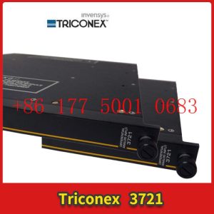
3201 TRICONEX nput/output communication card
3201 TRICONEX nput/output communication card
Module Clips Drive controller servo motor
Contact: Mr. Lai
Wechat:17750010683
Whats app:+86 17750010683
Skype:+86 17750010683
QQ: 3221366881
3221366881@qq.com
Ethernet IO module assists industrial robots
Industrial robots are multi joint robotic arms or multi degree of freedom machine devices aimed at the industrial field, which can achieve many material distribution, retrieval, pallets, and so on in industrial sites. However, due to the fact that many industrial six axes are equipped with 32 IO ports as standard, the IO ports are not sufficient in practical applications. Therefore, some DIN and DO extensions can be met through IO modules.
MQTT Ethernet IO Remote Module3201 TRICONEX nput/output communication card
The Modbus TCP Ethernet IO module has multiple channels, such as 4-way, 8-way, and 16-way switch input and output options. The communication protocol of the Ethernet IO module adopts the standard Modbus TCP protocol, Modbus RTU over TCP protocol, and MQTT protocol. Can support LAN configuration, with 1 DC power output to other devices on site, reducing the difficulty and cost of on-site wiring.
Most of the MQTT Ethernet IO modules should collect some IO port information and transmit data through the network port. In fact, the Ethernet IO module can not only serve as a TCP server, but also as a TCP client. In addition, it can not only count high-speed pulses but also output high-3201 TRICONEX nput/output communication cardspeed pulses. This is very convenient for doing some control processing on industrial sites, such as controlling servo motors and other scenarios! The most important thing is the data caching function. Even if the network is disconnected, it is not afraid. The data will be automatically cached, and after the network is restored, it will be automatically retransmitted.
The MxxxT industrial remote Ethernet I/O data acquisition module is embedded with a 32-bit high-performance microprocessor MCU, and integrates an industrial grade 10/100M adaptive Ethernet interface to support the standard Modbus protocol. It can easily integrate with third-party SCADA software, PLC, and HMI devices for application. Equipped with an RS485 interface, it has good scalability and can be cascaded with standard Modbus RTU I/O devices through the RS485 bus to achieve the combination of various digital, analog, and thermal resistance IO modules, saving costs. At the same time, this device has the function of cluster register mapping, and the data of the cluster is automatically collected into the mapping storage area of the local computer. The upper computer can respond quickly without waiting when querying, meeting the strict and timely functional requirements of industrial sites.
What is a remote IO module and what are its purposes
Technology is constantly evolving, and we can come into contact with various electronic devices both in daily life and in the workplace. And a large number of electronic devices work together to generate some signal sources. In order to better transmit and collect signals, industrial control products such as remote IO modules, signal transmitters, and signal acquisition modules have been developed.
In the past, people had to connect existing lines and boxes one at a time, which greatly increased the cost and construction time of cables. Moreover, if the distance was too long, they also had to face issues such as voltage attenuation. And through the remote IO module, this problem can be effectively solved.
If your cabinet is 200 meters away from the site and remote IO is not used, then you can extend each signal line by 200 meters and install the remote IO module on site, which can save you a lot of cable costs and reduce the complexity of construction.
In short, sometimes some IOs are set far away from the central control room and then connected back to the central control room through fiber optics to save on cable procurement and construction. Sometimes, the logical “remote” is because the allowed quantity of “local IO” cannot meet the actual needs, so it is necessary to connect to the “remote IO template”, which depends on the situation.
In addition, the general cabinet is placed on the equipment site. However, some control signals, such as emergency stop and bypass, are implemented in the control room, so remote IO modules need to be used to transmit these signals to the control system in the computer room.
What is an Ethernet IO module and what are its functions
The Ethernet IO module is a hardware gateway that adds IO to the network port.
The Ethernet IO module has hardware interfaces such as switches, analog signals, relays, RS485, RJ45, etc. Can be used for IO data collection network port transmission in industrial automation. Simply put, it refers to sensors with standard signals on site, or serial devices with 485 signals such as PLCs, which can be converted into real values through such gateways and then transmitted to the host for display through network ports.
1. Collect and control data for internal processing and transmit it to the external network through Ethernet
2. Support 4-way photoelectric isolation switch input
3. Supports 4 independent relay control outputs
4. Supports 8 analog inputs, 4-20mA or 0-5V/0-10V/0-30V (optional)
5. Support RS485 serial port data collection, with serial port server function
6. Supports Modbus RTU communication protocol and virtual serial port
7. Supports docking with various configuration software and TCP/UDP servers
What are the types of integrated IO modules3201 TRICONEX nput/output communication card
For a programmable logic controller, IO fulfills the responsibilities of data acquisition and instruction output. What control objectives can a PLC achieve, and the quantity and type of IO are crucial. For general integrated PLCs, the number and types of IO interfaces are constant. Some friends may ask, what if you encounter a complex control project with insufficient IO ports in the PLC? Don”t worry, nowadays PLCs have communication interfaces that can be connected to other IO couplers to achieve IO expansion. So, what are the types of IO modules that we can integrate in our daily lives? Actually, it can be mainly divided into four categories, namely:
1. Digital signal acquisition IO can achieve discontinuous signal acquisition, and a typical IO type is a counter input IO module.
Technology Oasis • Source: Guangcheng CAN Bus • Author: Guangcheng CAN Bus • 2022-05-09 09:52 • 1740 readings
For a programmable logic controller, IO fulfills the responsibilities of data acquisition and instruction output. What control objectives can a PLC achieve, and the quantity and type of IO are crucial. For general integrated PLCs, the number and types of IO interfaces are constant. Some friends may ask, what if you encounter a complex control project with insufficient IO ports in the PLC? Don”t worry, nowadays PLCs have communication interfaces that can be connected to other IO couplers to achieve IO expansion. So, what are the types of IO modules that we can integrate in our daily lives? Actually, it can be mainly divided into four categories, namely:
1. Digital signal acquisition IO can achieve discontinuous signal acquisition, and a typical IO type is a counter input IO module.
2. Digital output IO, which can send out command signals of digital quantities to control actuators, such as PWM IO, can send pulse signals to control servo motors and stepper motors. In addition to PWM IO, we often use relay output type IO.
3. After discussing digital IO, let”s talk about analog IO. Firstly, analog input IO includes voltage analog input IO, current analog input IO, temperature analog input IO, etc. They collect continuous signals.
4. Finally, there is the output type IO of analog quantity, mainly including voltage analog quantity output type IO and current analog quantity output type IO. Some friends may ask why there is no temperature this time, but there are relatively few applications, mainly based on voltage and current types.3201 TRICONEX nput/output communication card
Industrial automation solutions, starting with remote IO modules!
The remote IO module is mainly used for collecting analog and digital signals on industrial sites, and can also output analog and digital signals to control equipment. It is possible to expand the input and output ports of data processing equipment such as PLCs and collection instruments. For example, a PLC only has 10 analog input interfaces, but if 30 analog quantities need to be collected on site, remote IO expansion needs to be added.
Furthermore, due to the distance between the equipment and the main control PLC or industrial computer, RS-485 bus is usually used for transmission. There are also some factories with high levels of automation that use industrial Ethernet to control remote IO modules. In the past, when laying lines between equipment and cabinets, people had to connect them one by one, which greatly increased the cost of cables and construction time. Moreover, if the distance was relatively long, they also faced problems such as voltage attenuation. And with the remote IO module, it effectively solves this problem. If your cabinet is 200 meters away from the site and you do not use remote IO, then you need to lay out each signal line for 200 meters. Installing the remote IO module on site can save you a lot of cable costs and reduce the complexity of construction from a cost perspective.
Simply put, sometimes some IO is set up in the on-site device cluster, which can be connected to the PLC through a communication cable to send the signal to any place where it is needed, saving wiring and PLC”s own IO points. Sometimes, the logical “remote” is because the allowed number of “local IO” cannot meet the actual needs, and it needs to be connected to the “remote IO template”, depending on the actual situation.
In addition, the general cabinet room is located on the device site. But some control signals, such as emergency stop and bypass, are implemented in the control room, so remote IO modules need to be used to send these signals to the control system in the cabinet room.
Why use remote I/O?
1. Because in some industrial applications, it is impossible to install PLCs with local I/O modules near on-site equipment due to harsh environments.
2. When you want to place the I/O module near the field device to eliminate long multi-core cables, you can receive signals from distant sensors and send remote control signals to control valves, motors, and other final actuators. The signal can be transmitted at any distance using various transmission protocols such as Ethernet and Profibus through high-speed media such as twisted pair and fiber optic.
3. Multiple transmission protocols such as Ethernet and Profibus can be used to send signals at any distance on high-speed media such as twisted pair and fiber optic.
The barium rhenium technology MXXT remote IO module uses industrial grade components with a wide working voltage of DC9-36V, which can operate normally within the range of -20~70 ℃. It supports RS485/232 communication mode, and the communication protocol adopts standard Modbus TCP protocol, Modbus RTU over TCP protocol, and MQTT protocol. We strive to fully meet the needs of our customers with an electrical and mechanical system that is anti-interference, resistant to harsh environments, and compatible with general use. It has stable performance, reliable quality, short delivery time, and fast response.
Advantages of Barium Rhenium Remote I/O Module
1. It can be controlled by remote commands.
2. Save the cost of using industrial control computers and IO cards, and Ethernet I/O modules can be directly connected to the upper computer system;
3. Replacing 4-20mA signal transmission with 10/100MHz Ethernet transmission has improved transmission speed;
4. Replacing various instrument controller signal lines with an Ethernet cable reduces the attenuation of remote signal transmission;
5. The signal cable of the instrument controller only needs to be connected to the Ethernet I/O module, greatly reducing cable costs and wiring workload.
6. Convenient installation method. Rail installation, high reliability, strong anti-interference ability, and more convenient on-site installation.
What are the characteristics of a demonstration system based on IO Link slave stations
IO Link is an industrial communication interface that is independent of any fieldbus and suitable for simple sensors and actuators at the lowest level of industrial control. The IO Link system includes IO Link devices (such as sensors and actuators), IO Link master stations, and cables for standard sensors. The system structure is shown in Figure 1. For example, when a remote IO module compatible with EtherNet/IP serves as the master station, in addition to standard I/O signals, the module sends and receives configuration data, diagnostic data, or enhanced process data through a pulse modulation process, which is then packaged into EtherNet/IP data packets and finally transmitted to the network master station, usually a PLC. In the above applications, the connection between remote I/O and IO Link devices remains the same as that of traditional discrete devices. The advantage of IO Link mainly lies in its greater information exchange capability, which was previously impossible to achieve with standard I/O devices. Another advantage of IO Link is that it does not rely on any fieldbus, and through any I/O module that complies with the IO Link protocol (including local I/O and remote I/O), IO Link sensors or actuators can be integrated into any fieldbus system.
In order to further study the architecture, communication mechanism, and development application of the IO Link system, an IO Link slave toolkit can be designed and developed, including a universal development module for IO Link, an IO Link analysis tool, and an IO Link slave protocol stack. The IO Link universal development module is the foundation for this work and also serves as a bridge between the IO Link master station and equipment signals. The IO Link analysis tool can help developers and testers analyze communication details to identify and solve problems. The IO Link slave protocol stack is a firmware library that provides a hardware abstraction layer and application program interface, allowing developers to easily and quickly develop IO Link slave products on various microprocessor platforms. The IO Link slave station studied in this article only focuses on digital (button) signal input and digital signal output (indicator light). The design of the IO Link universal development module only needs to be expanded on this basis to have the ability to process analog signals.
The IO Link Master module used in this article, USB IO Link Master, can connect IO Link devices to a PC, which can be configured and tested through the IO Link Device Tool software or demonstrated device functionality. IO Link devices must be described through a device description file (IODD file), which includes a set of XML text files and PNG graphic files, which contain information about device identification, communication characteristics, parameters, process data, and diagnostic data. The portion within the elliptical dashed line in Figure 2 is an IO Link three wire cable, with L+/I – being a 24 V DC power supply and C/Q being a signal line used to transmit process data, diagnostic data, configuration data, etc. The IO Link universal development module is mainly composed of data transceivers and microprocessors. It can process input signals from sensors and transmit information to the IO Link master station. It can also receive and process data information from the master station and transmit it to the actuator. The IO Link analysis tool can help developers view, record, analyze data, and understand communication details. This part of the design is not discussed in this article.
Introduction to IO Link Communication Mode3201 TRICONEX nput/output communication card
IO Link devices can operate in SIO mode (standard I/O mode) or IO Link mode (communication mode). After power on, the device always operates in SIO mode. The port of the main station has different configuration methods. If configured in SIO mode, the main station considers the port as a standard digital input. If configured in communication mode, the main station will automatically identify the communicable devices for communication.
2.1 Data Types3201 TRICONEX nput/output communication card
The three basic data types for IO Link communication are periodic data (or process data PD), non periodic data (or service data SD), and event.
The process data (PD) of the device is transmitted periodically in the form of a data frame, while service data (SD) is only exchanged after the master station issues a request. Figure 3 shows a typical IO Link message structure. When an event occurs, the “event flag” of the device is set, and the main station reads the reported event (service data cannot be exchanged during the reading process) upon detecting the setting. Therefore, events such as pollution, overheating, short circuits, or device status can be transmitted to the PLC or visualization software through the main station
2.2 Parameter data exchange
Since service data (SD) must be transmitted through PLC requests, SPDU (Service Protocol Data Unit) is defined. In the main station, requests for read and write services are written to SPDU and transmitted to devices through the IO Link interface.
The general structure of SPDU is shown in Figure 4, and its arrangement order is consistent with the transmission order. The elements in SPDU can take different forms depending on the type of service. SPDU allows access to data objects that are intended for transmission, while Index is used to specify the address of the requested data object on the remote IO Link device. In IO Link, there is a term called direct parameter page, which stores parameter information such as minimum cycle time, supplier ID, and master station commands. The data objects accessible in the direct parameter page can be selectively provided through SPDU.
HMT7742 is an IO Link slave transceiver chip that serves as a bridge between the MCU of external sensors or actuators and the 24V signal line that supports IO Link communication. When the IO Link device is connected to the master station, the master station initializes communication and exchanges data with the MCU. HMT7742 serves as the physical layer for communication.
Due to the fact that the three indicator lights (rated voltage 24 V) controlled by the output port of the MCU are powered by the IO Link power cord, it is necessary to monitor the current on the power cord in order to trigger appropriate corrective measures when the current exceeds a set threshold, such as removing the indicator lights from the IO Link power cord. The current monitoring module uses an INA194 current detection amplifier. As a high detection current detector, INA194 is directly connected to the power supply and can detect all downstream faults. It has a very high common mode rejection ratio, as well as a large bandwidth and response speed. It can amplify the voltage on the induction resistor 5O times and output it to the forward input terminal AIN0 of the MCU internal voltage comparator. When the voltage value of AIN0 exceeds the threshold set at the reverse input terminal, By controlling the low level output of PB0, the indicator LAMP can be cut off from the IO Link power line to achieve overcurrent protection function. This part of the circuit is shown in Figure 6.
What is the function of an IO chip
Io generally refers to input and output devices, where I is the input and O is the output. The input to the IO port of the chip is the external signal transmission to the chip, while the output is the internal signal transmission to other devices. The input and output are relative. In short, in a broad sense, the control of input and output interfaces is called an IO chip, and network cards are also considered IO or array cards.
The CPU must read and write data to external registers or ROMs on RAM or other hardware through IO commands (such as input/output commands). For example, reading a keyboard involves accessing external registers on the keyboard through the 60H port, and the chip on the keyboard scans the keyboard. Pressing or holding down a key for a long time will cause the chip to generate corresponding scan or break codes, which will be written to the external register of the 60H port, so that the CPU can achieve the purpose of controlling the keyboard. Therefore, I think IO chips should refer to a large category. The CPU already has powerful IO instructions and corresponding control buses.
51 microcontroller IO port input and output mode_ Four usage methods for IO ports
The traditional 51 microcontroller IO interface can only be used as a standard bidirectional IO interface. If it is used to drive LED, it can only be driven by injecting current or using a transistor external expansion drive circuit.
Current injection method: LED positive pole connected to VCC, negative pole connected to IO port. If the IO is at a high level, the two poles of the LED are at the same level, and there is no current, the LED will turn off; IO is at low power level, current flows from VCC to IO, and LED lights up. But when you connect the positive pole of the LED to the IO interface and the negative pole to GND, placing the IO interface at a high level will cause the LED to light up. However, due to the insufficient pull-up capability of the IO interface, the brightness is not ideal. The following method can be used to solve this problem.
Push-pull working mode: The positive and negative poles of the LED are connected to two IO ports, and then the positive IO interface is set as the push-pull output, while the negative IO interface is set as the standard bidirectional current input. The push pull method has strong pull-up ability and can achieve high-level LED driving.
Four usage methods for IO ports3201 TRICONEX nput/output communication card
From the perspective of the characteristics of the I/O port, the P0 port of Standard 51 is an open drain structure when used as an I/O port, and in practical applications, a pull-up resistor is usually added; P1, P2, and P3 are all quasi bidirectional I/Os with internal pull-up resistors, which can be used as both input and output. The I/O port characteristics of the LPC900 series microcontroller have certain differences, and they can be configured into four different working modes: quasi bidirectional I/O, push pull output, high resistance input, and open drain.
Compared with Standard 51, the quasi bidirectional I/O mode differs in internal structure but is similar in usage. For example, when used as an input, it must first write “1” to set it to high level before reading the level state of the pin.!!!!! Why is it like this? Please refer to the diagram below for analysis.
The characteristic of push-3201 TRICONEX nput/output communication cardpull output is that it can drive a large current regardless of whether it outputs high or low levels. For example, when outputting high levels, it can directly light up the LED (by connecting several hundred ohm current limiting resistors in series), which is difficult to achieve in quasi bidirectional I/O mode.
The characteristic of high impedance input mode is that it can only be used as an input, but it can obtain relatively high input impedance, which is necessary in analog comparator and ADC applications.
The open drain mode is similar to the quasi bidirectional mode, but there is no internal pull-up resistance. The advantage of open drain mode is good electrical compatibility. If the external pull-up resistor is connected to a 3V power supply, it can interface with a 3V logic device. If the pull-up resistor is connected to a 5V power supply, it can also interface with a 5V logic device. In addition, the open drain mode can also conveniently implement the “line and” logic function.
For the explanation of the above question, there is this information:
High resistance state is a common term in digital circuits, referring to an output state of a circuit that is neither high nor low. If the high resistance state is input into the next level circuit, it has no impact on the lower level circuit, just like not connected. If measured with a multimeter, it may be high or low, depending on what is connected afterwards.
High resistance states can be understood as open circuits during circuit analysis. You can think of it as having a very high output (input) resistance. His limit can be considered suspended.
Typical applications of high resistance states:
1. On the bus connected structure. There are multiple devices hanging on the bus, and the devices are connected to the bus in a high impedance form. This automatically releases the bus when the device does not occupy it, making it easier for other devices to gain access to the bus.
2. Most microcontroller I/O can be set to high impedance input when used, such as Lingyang, AVR, and so on. High resistance input can be considered as having infinite input resistance, indicating that I/O has minimal impact on the preceding stage and does not generate current (without attenuation), and to some extent, it also increases the chip”s resistance to voltage surges.
1.Has been engaged in industrial control industry for a long time, with a large number of inventories.
2.Industry leading, price advantage, quality assurance
3.Diversified models and products, and all kinds of rare and discontinued products
4.15 days free replacement for quality problems
ABB — AC 800M controller, Bailey, PM866 controller, IGCT silicon controlled 5SHY 3BHB01 3BHE00 3HNA00 DSQC series
BENTLY — 3500 system/proximitor, front and rear card, sensor, probe, cable 3500/20 3500/61 3500/05-01-02-00-001 3500/40M 176449-01 3500/22M 138607-01
Emerson — modbus card, power panel, controller, power supply, base, power module, switch 1C31,5X00, CE400, A6500-UM, SE3008,1B300,1X00,
EPRO — PR6423 PR6424 PR6425 PR6426 PR9376 PR9268 Data acquisition module, probe, speed sensor, vibration sensor
FOXBORO — FCP270 FCP280 FCM10EF FBM207 P0914TD CP40B FBI10E FBM02 FBM202 FBM207B P0400HE Thermal resistance input/output module, power module, communication module, cable, controller, switch
GE —- IS200/215/220/230/420 DS200/215 IC693/695/697/698 VMICPCI VMIVME 369-HI-R-M-0-0-E 469 module, air switch, I/O module, display, CPU module, power module, converter, CPU board, Ethernet module, integrated protection device, power module, gas turbine card
HIMA — F3 AIO 8/4 01 F3231 F8627X Z7116 F8621A 984862160 F3236 F6217 F7553 DI module, processor module, AI card, pulse encoder
Honeywell — Secure digital output card, program module, analog input card, CPU module, FIM card
MOOG — D136-001-007 Servo valve, controller, module
NI — SCXI-1100 PCI – PXIE – PCIE – SBRIO – CFP-AO-210 USB-6525 Information Acquisition Card, PXI Module, Card
Westinghouse — RTD thermal resistance input module, AI/AO/DI/DO module, power module, control module, base module
Woodward — 9907-164 5466-258 8200-1300 9907-149 9907-838 EASYGEN-3500-5/P2 8440-2145 Regulator, module, controller, governor
YOKOGAWA – Servo module, control cabinet node unit
Main products:
PLC, DCS, CPU module, communication module, input/output module (AI/AO/DI/DO), power module, silicon controlled module, terminal module, PXI module, servo drive, servo motor, industrial display screen, industrial keyboard, controller, encoder, regulator, sensor, I/O board, counting board, optical fiber interface board, acquisition card, gas turbine card, FIM card and other automatic spare parts