")
Description
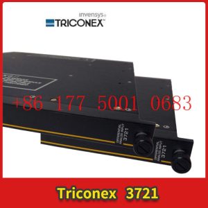
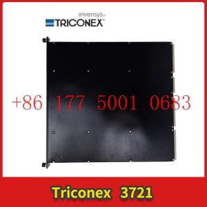
3005 TRICONEX controller
3005 TRICONEX controller
Module Clips Drive controller servo motor
Contact: Mr. Lai
Wechat:17750010683
Whats app:+86 17750010683
Skype:+86 17750010683
QQ: 3221366881
3221366881@qq.com
What IO combinations can a mini PLC combine with to achieve automated control?
At present, there are two main design modes for controllers like PLC, one is integrated design and the other is modular design. From the name, we can feel that there are two different PLCs, one that cannot be disassembled and the other that can be disassembled. Due to the fact that the main control module and IO module of the modular PLC can be spliced as needed, its volume and weight are usually very small, and we cannot call it a mini PLC too much. So, what IO combinations can such a small gadget combine with to achieve automation control? Let”s take a brief inventory:3005 TRICONEX controller
1. Firstly, there is the digital quantity acquisition IO module, which is used to collect digital quantity information. Typical examples include counter IO, PNP type digital quantity acquisition IO, NPN type digital quantity acquisition IO, etc.
2. Then there is the digital output IO module, which is used to send digital instructions. The most typical example is PWM output IO, which can output pulse signals to control servo motors or stepper motors for operation.
3. After talking about digital IO, let”s talk about analog IO. Analog signal acquisition type IO includes voltage signal acquisition, current signal acquisition, and temperature signal acquisition. The IO for collecting temperature signals includes PT100, PT1000, and various thermocouple temperature acquisition modules.
4. Finally, there are analog output IO, as well as output current signals and voltage signals.
In addition to the above IO modules, our modular PLC also supports extended communication interfaces, further enhancing the equipment”s scalability.
Module Input/Output (I/O) Knowledge3005 TRICONEX controller
Module Input/Output (I/O) Knowledge
I think it”s necessary to talk about the sorting of the input and output ports of the module. Generally, we can divide it into IO functional division and IO specifications.
The purpose of the former is mainly to convert all functions into actual division into MCU IO ports, while the purpose of the latter is to determine the specifications of all IO ports. Of course, you can completely skip these tasks, and it”s also possible. Depending on the company”s requirements, I think individuals still consider them as a work habit.
The following examples are all created for my blog post. If there are any duplicate names, please do not contact me.
Looking at the above figure, first determine all input and output functions and power input, as well as communication.
Then separate the power distribution with different lines, and start organizing each power supply line and processing process. The final purpose of the entire diagram is to clearly allocate the input and output sequence.
The IO specification is to provide a detailed description of all interfaces, crystal oscillators, and other information to the MCU.
1. Enter the number of low effective interfaces and how much pull-up resistance (switch wet current) is required (how much current does the microcontroller need to absorb, which may be injected into the microcontroller after pull-up).
2. Enter the number of highly effective interfaces, how many pull-down resistors are required (switch wet current), (how much current does the microcontroller need to absorb, and it is possible to inject the microcontroller after the switch is effective)
3. Number of analog input interfaces, evaluate whether the analog ports of the microcontroller are sufficient, and confirm the required analog conversion accuracy. Evaluate whether the A/D conversion reference voltage needs to be replaced (to meet accuracy requirements). Consider how many power supplies need to be tested and how many analog input ports are configured.
4. Evaluate the requirements for crystal oscillator accuracy and whether a phase-locked loop is required.
The above requirements are mainly aimed at module design and need to be confirmed during the early development of the module. All requirements can be organized using an Excel table and displayed in the diagram.
Distributed dual Ethernet IO module
The distributed dual Ethernet IO module adopts an industrial grade design, which meets the demanding industrial application scenarios. It is equipped with a dedicated high-performance Ethernet chip, which can quickly achieve cascade networking between IO modules without the need for repeated wiring, saving on-site wiring costs.
The distributed dual Ethernet IO module comes with switch input, switch output, relay output, analog input, analog input, thermal resistance input, etc. It supports high-speed pulse input counting and high-speed pulse output, and is designed specifically for industrial field data collection, measurement, and control. The distributed dual Ethernet IO module supports Modbus TCP protocol and Modbus RTU protocol for uplink, which can quickly connect to existing DCS, SCADA, PLC, HMI and other systems. The distributed dual Ethernet IO module supports one RS485 interface and supports Modbus RTU Master function. It can expand the IO module, read and write intelligent instrument data, or connect to HMI, DCS, PLC and other devices as a Modbus Slave.
Is it better to have a higher number of IO module bit widths?
IO is an important component of PLC, and the collection of PLC information and the output of instructions must be applied to various input and output IO. I don”t know if you have read some IO user manuals. One of their instructions is the device”s bit width, such as 12 bits and 16 bits. So, is it better to have a higher number of bit widths for the IO module? Let”s talk about this matter.
Bit width is the number of bits of data that can be transmitted within a clock cycle, and the larger the number of bits, the greater the amount of data that can be transmitted instantly. From this perspective, the larger the bit width of the IO module, the better. This is not a problem. However, the amount of data transmission, also known as data bandwidth, depends not only on the bit width, but also on the frequency of data transmission. The multiplication of the two is the final total amount of data transmitted. That is to say, even if the light position is wide, but the frequency is too high, it still cannot work. At the same time, the larger the bit width, the higher the hardware cost, and the greater the heat generation and power consumption of the device.
How to Apply Ethernet IO Module to Weighbridge Data Collection3005 TRICONEX controller
Weighbridge, a large scale set on the ground, usually used to weigh the tonnage of cargo carried by a truck. It is the main weighing equipment used for measuring bulk goods in factories, mines, merchants, etc. The MXXXX series of Ethernet IO modules with barium rhenium technology have rich IO ports that can be used to assist in data collection and transmission of the weighbridge, quickly achieving comprehensive management of data and control.
Before the vehicle enters the weighbridge, there will be an infrared sensor scanning about a few hundred meters. The infrared sensor will output a switch signal to the Ethernet IO module, indicating that a vehicle needs to enter. Before the vehicle officially enters the weighbridge for weighing, there will be an infrared barrier sensor scanning, and the barrier will also output a switch signal to the Ethernet IO module. When the vehicle is completely parked in front of the weighbridge (including whether the position is correct), the central control room will decide whether to start weighing based on the information received by the IO module from the radar sensor. Finally, the vehicle is weighed and drives away from the weighbridge. The scanning signal from the infrared barrier sensor at the exit is transmitted to the IO module, and the central control room controls the IO port of the IO module to open (close) the barrier. The green light will light up, and the vehicle will fully exit and leave the weighing weighbridge. The entire weighing process requires only one Ethernet IO module to collect information and control actions.3005 TRICONEX controller
The MxxxT industrial remote Ethernet I/O data acquisition module adopts an industrial grade circuit design. The digital input adopts optocoupler isolation, providing 12 pulse counting inputs, supporting dry and wet contact input types. The analog input adopts operational amplifier isolation, supporting 12 bit high-precision data acquisition, compatible with 0~5V, 0~10V, 0~20mA, and 4~20mA input types. The DO output is a transistor Sink output, providing one channel of high-speed pulse output, The thermal resistance RTD input supports two types: PT100 and PT1000, and the analog AO output supports 0-10VDC output.
Pocket Io ™ The development platform has opened up numerous new avenues for experiencing the full power of Industry 4.0.
Compact design: compact structure, ultra small size, and overall dimensions (10 cubic inches: 3.5 “x 3.5” x 0.8 “).
Reliable and safe technology: Composed of advanced industrial products, all products have a rated working environment temperature of -40 ° C to+125 ° C, fully utilizing Maxim”s reliable, safe, and fast demagnetization technology.
Efficient: Ensure low power consumption and improve efficiency – no need for cooling fans.
Integrate numerous powerful interfaces: provide a complete set of 30 IOs for controlling the entire manufacturing node or a certain device, including: 4 analog inputs, 1 analog output, 8 digital inputs, 8 digital outputs, 2 RS-485 (compatible with Profibus fieldbus), 3 encoder/electrical control ports, and 4 IO Link hosts.
Long battery life: Firstly, the compact and portable PLC platform can work for up to 2 hours using “AA/AAA” type batteries, and 8 hours using LiFePO4 rechargeable batteries.
Programmable: It can be programmed through Arduino Sketch or using Intel”s Edison Eclipse IDE tool, supporting Windows, Linux, or Mac OS operating systems.
Easy to use: Sketches can be converted into apps and then downloaded to iPads ® Or iPhone ® (Converted to an HMI panel for controlling Pocket IO).
What are the advantages of Ethernet remote IO modules that can be cascaded?
Advantages and specific application scenarios of Ethernet remote IO modules that can be cascaded
For scenarios where data collection control points are linearly distributed, such as streetlights, bridges, streetlights, digital factories, parking lot parking monitoring, smart parking lots, smart parking racks, and building automation control systems in smart parks, using cascading dual Ethernet remote IO modules saves more costs than using single Ethernet remote IO modules.
The Ethernet remote IO module that can be cascaded is a new type of Ethernet remote IO module that supports MAC layer data exchange and can achieve hand in hand connection. This not only saves switch interfaces, but also reduces a large amount of Ethernet cable costs, wiring space, and wiring costs.
Its advantages are as follows:
1. No need for a large number of Ethernet switches or occupying Ethernet switch ports;
2. It can save a lot of Ethernet cables, cable space, and labor costs for installing cables;
3. The overall cost has significantly decreased;
4. Supports both Modbus RTU protocol, Modbus TCP protocol, and the Internet of Things protocol MQTT protocol;
5. Support TCP Server and TCP Client services;
6. Can be connected to SCADA systems, PLC systems, or cloud platforms;
7. The series uses a MAC layer for data exchange, ensuring that network connectivity does not cause communication issues with subsequent devices due to device failures in the middle.
The comparison between cascaded Ethernet remote IO modules and traditional IO modules used in building automation systems is shown in the following figure:
1. Adopting a cascaded dual Ethernet remote IO module, data acquisition and control wiring for floors with a height of 70 meters only requires a 70 meter Ethernet cable;
2. Using a traditional single Ethernet remote IO module, the data acquisition and control system wiring for a 70 meter high floor requires a 280 meter Ethernet cable.
It can be seen that using cascaded dual Ethernet remote IO modules can save a lot of wiring costs compared to traditional single Ethernet remote IO modules.
Application of IO Link in Industrial Automation
This article mainly introduces the overall solution of ST IO Link communication master station used in industrial systems, including the following 5 aspects:
Firstly, the application of IO Link in industrial automation; The second is the introduction of ST IO Link main station transceiver; The third is the introduction of our ST”s IO Link main site evaluation board; The fourth is an introduction to the reference design scheme of the IO Link main station; The fifth is a demonstration of the IO Link master station reference design.
The industrial automation system can be said to be composed of many levels. The top level is usually industrial Ethernet to transmit data to the upper control center or monitoring center of the factory, while the middle layer is usually some PLC system for specialized process processing, such as controlling a specialized assembly line or production line. At the bottom, there are usually many industrial sensors, such as temperature sensors, pressure sensors, flow sensors, or proximity sensors, as well as some actuators, such as valves, moving lights, relays, or contactors, which are used for collecting and controlling physical quantities.
Between these levels, there will also be some modules or gateways for conversion and processing work. Therefore, in traditional industrial systems, there are many different level standards and communication protocols on site, resulting in poor modularity and versatility. Because there are both analog signals on site, such as a 4 to 20 mA current loop and analog voltage signals, as well as digital signals. In such an environment, analog signals are particularly susceptible to interference from harsh on-site environments. At the same time, sensors or actuators for analog transmission cannot perform on-site remote configuration or calibration 3005 TRICONEX controller diagnosis work. In order to solve the transmission of the last segment of data to sensors and actuators in industrial field environments, as described earlier, we have introduced a specialized digital interface IO Link to achieve fully digital transmission between the interface modules of sensors and industrial field buses. The bidirectional data transmission makes it possible to parameterize the interaction of on-site data, diagnose and transmit information. By using this technology, remote condition monitoring and predictable maintenance of terminal equipment can be achieved, thereby effectively alleviating the problem of production line downtime.
Its advantages include:3005 TRICONEX controller
Firstly, whether it is a pure digital sensor, an analog sensor after digital quantization, or different types of actuators, unified access can be achieved, thus achieving a simplified and standardized system architecture. Secondly, the transmission of digital signals will have stronger anti-interference ability than the transmission of analog signals, so the reliability of the system will also be stronger. Thirdly, through the bidirectional transmission of digital signals, more intelligent and advanced actuators or sensors can be used, making it easier to achieve status monitoring and system diagnostic protection functions. In this way, any issues and status of the production line can be monitored and maintained in real-time, ensuring the reliability, maintainability, and upgradability of the entire production line, thereby ensuring the minimum downtime.
The following is the specific content about IO Link technology
Firstly, the definition of the IO LINK standard enables data transmission, processing, configuration, and diagnostic information exchange between sensors or actuators and control systems. Secondly, this is a simple peer-to-peer communication architecture, where a master port is connected to a device port. Then, it can achieve compatibility with existing communication architectures, such as reusing cables and interfaces. At the same time, the IO Link system also has backward compatibility upgrade capability, as the master end of the system uses digital binary serial communication to interact with devices, and vice versa.
It can be said that IO link makes the system simpler:
Firstly, this is a universal standard communication method that complies with IEC61131-9. Secondly, IO Link is an intelligent communication system that solves the digital information exchange and transmission of the last distance from the control host to the terminal device. Thirdly, IO Link is simple to use and can be said to be plug and play, compatible with some existing system devices.
Some related products and solutions provided by ST in IO Link communication solutions
Firstly, in this communication system, the IO Link Master, which connects to the upper computer controller, is one of the main key solutions that will be mentioned later. Secondly, ST can provide some communication chips on the IO Link Master project, such as L6360. On the other side of the sensor or actuator end, namely the IO Link Slave end, ST can provide communication chips L6362A and L6364 on this IO Link Slave slave project. According to standards, this three-wire point-to-point communication method is easily compatible with some existing sensor actuators” standard ports, such as M12 standard industrial connectors and M12 standard connector wires. In addition, its advantages include the ability to achieve point-to-point bidirectional signal transmission within a single cable, as well as the general power supply requirements of the master end to the sensor actuator. According to the general requirements of the current industry, the maximum length of this cable is 20 meters, and the three wires inside are 24V, 0V, and data cables. The L+of this chip can support up to 500 milliamperes. If greater current is needed, there are also other L+drivers, including Load Switch IPS and other products, which can provide greater current or can be applied externally. The IO Link communication speed can generally reach a baud rate of 230.4K per COM3, and it also has functions such as status indication and detection.
For some specific application characteristics of IO Link, the communication transceiver system composed of L6360 and L6362A can support three standard data types of IO Link, namely COM1 (4.8k), COM2 (38.4K), and COM3 (230.4K) modes. This communication system can meet the requirements of all modern standards, industrial sensors, and actuators: firstly, it can quickly and very easily configure or reconfigure sensors or actuators. Secondly, it can be widely applied to various standardized sensors or systems that execute information. Thirdly, as a digital communication system, compared to traditional analog signal transmission systems, it can reduce power consumption and improve system efficiency. Fourthly, it has complete diagnostic and protection functions, which can improve the reliability of related systems. Therefore, it can be widely used to drive various digital sensors and actuators, as well as input and output modules of PLC, in order to achieve and meet various requirements of Industry 4.0.
How to Determine the Interference Problem of PROFINET IO Communication
Preliminary Diagnosis of PROFINET Interference Problems
1. Overview
When debugging PROFINET IO communication, it is common to encounter communication failures. One of the reasons for communication failures is interference. PROFINET IO communication equipment often operates in complex industrial electromagnetic environments, and incorrect shielding grounding or non-standard installation may lead to communication interference problems. Since optical signals are not affected by electromagnetic interference, this article only introduces interference problems with electrical signals.
2. How to determine interference issues
If PROFINET IO communication is affected by electromagnetic interference, a simple judgment can generally be made through the following aspects:
2.1. Judging the communication status through PROFINET IO
If the following communication phenomena are found during PROFINET IO communication debugging or operation, it may be affected by electromagnetic interference:
① Occasionally, communication is interrupted and restored.
② When certain on-site devices or specific operations are turned on, communication is interrupted, and on the contrary, communication returns to normal.
2.2. By using STEP7 online diagnostic information to determine and view the diagnostic buffer information of the IO controller, how to detect the presence of frequent communication failures and recovery information between the IO controller and IO devices in the diagnostic buffer, as shown in the following figure, may be affected by electromagnetic interference:
14 STEP7 Device Diagnostic Buffer Information
3. How to troubleshoot and solve interference problems
If a suspected electromagnetic interference causing PROFINET IO communication failure is found, how should we troubleshoot and solve it? The following will be introduced from the following aspects:
3.1 Increase PROFINET IO communication watchdog time
Due to PROFINET IO communication failure occurring during watchdog time, the IO controller did not provide input or output data (IO data) to the IO device, and watchdog time=the number of update cycles allowed for IO data loss × The refresh time is usually automatically calculated and allocated by the IO controller. This time value is generally small. If electromagnetic interference is encountered, the probability of communication failure occurring within the automatically calculated watchdog time will increase. At this time, we can appropriately increase the PROFINET IO communication refresh time or the number of update cycles allowed for IO data loss to increase the watchdog time. However, this method may not solve serious electromagnetic interference problems, and it is recommended to eliminate and solve them through subsequent methods.
How to Build High Channel Density Digital IO Modules for the Next Generation Industrial Automation Controllers
With the rapid development of industrial automation, digital IO modules have become an indispensable part of industrial automation controllers. The digital IO module can connect the controller with external devices, such as sensors, actuators, etc., to achieve monitoring and control of industrial production processes. However, with the continuous development of industrial automation, digital IO modules need to have higher channel density and stronger functionality to meet the needs of new industrial automation controllers. Therefore, it is very important to build high channel density digital IO modules for the next generation of industrial automation controllers.
The digital IO module is one of the most fundamental modules in industrial automation controllers, and its main function is to connect the controller with external devices to achieve signal input and output. The digital IO module usually includes two parts: a digital input module and a digital output module. The digital input module can convert the digital signals of external devices into signals that the controller can read, while the digital output module can convert the digital signals output by the controller into signals that external devices can read. The channel density of a digital IO module refers to the number of digital input or digital output channels provided on the module, which is the input and output capacity of the module.
With the development of industrial automation, digital IO modules need to have higher channel density and stronger functions to meet the needs of new industrial automation controllers. The following are several aspects to consider when building a high channel density digital IO module for the next generation of industrial automation controllers:3005 TRICONEX controller
1. Choose the appropriate communication protocol
Digital IO modules typically communicate with controllers through communication protocols, so choosing a suitable communication protocol is crucial. Common communication protocols include Modbus, Profibus, CANopen, Ethernet, etc. Different communication protocols have different advantages and disadvantages, and selecting a suitable communication protocol requires considering the following factors:
(1) Communication speed: The faster the communication speed, the shorter the response time of the digital IO module, which can process input and output signals faster.
(2) Communication distance: The farther the communication distance, the wider the application range of digital IO modules.
(3) Reliability: The reliability of communication protocols determines the stability and reliability of digital IO modules.
(4) Cost: Different communication protocols have different costs, and suitable communication protocols need to be selected based on actual needs.
2. Choose the appropriate digital IO chip
The digital IO chip is the core component of the digital IO module, and its performance and function directly affect the channel density and function of the digital IO module. Choosing a suitable digital IO chip requires considering the following factors:
(1) Channel density: The channel density of digital IO chips determines the channel density of digital IO modules, and channel density needs to be selected based on actual needs.
(2) Input/output type: Digital IO chips usually support digital input and digital output, and some chips also support functions such as analog input and output, counters, etc.
(3) Speed: The speed of the digital IO chip determines the response speed of the digital IO module, and it is necessary to choose a chip with a faster speed.
(4) Accuracy: The accuracy of digital IO chips determines the signal accuracy of digital IO modules, and it is necessary to choose chips with higher accuracy.
(5) Cost: Different digital IO chips have different costs, and suitable chips need to be selected based on actual needs.
3. Optimize circuit design
The circuit design of digital IO modules has a significant impact on their performance and stability. In order to improve the channel density and functionality of digital IO modules, it is necessary to optimize circuit design, such as:
(1) Using high-speed digital IO chips: Using high-speed digital IO chips can improve the response speed and accuracy of the module.
(2) Adopting anti-interference design: In order to improve the stability of the digital IO module, it is necessary to adopt anti-interference design, such as using filters, isolators, etc.
(3) Using optimized PCB layout: Optimizing PCB layout can reduce noise and interference in digital IO modules, improve module performance and stability.
4. Choose the appropriate shell material and size
Digital IO modules typically need to be installed in cabinets or control cabinets, so choosing the appropriate housing material and size is crucial. The shell material should have good protective and heat dissipation properties to protect the circuits of the digital IO module from external environmental influences. The shell size should be able to adapt to different installation environments, such as cabinets, control cabinets, etc.
5. Optimize software design
The software design of the digital IO module determines its functionality and performance. In order to achieve high channel density and stronger functionality, it is necessary to optimize software design, such as:
(1) Supporting multiple input and output types: Supporting multiple input and output types can meet different application needs, such as digital input and output, analog input and output, counters, etc.
(2) Supporting multiple communication protocols: Supporting multiple communication protocols can adapt to different controllers and application environments.
(3) Support for online debugging and monitoring: Supporting online debugging and monitoring can facilitate user diagnosis and maintenance of modules.
(4) Support for expansion function: Supporting expansion function can increase the functionality and application range of the module while ensuring channel density.
In summary, building a high channel density digital IO module for the next generation of industrial automation controllers requires multiple considerations, including selecting suitable communication protocols, selecting suitable digital IO chips, optimizing circuit design, selecting suitable shell materials and sizes, and optimizing software design. Only by comprehensively considering these factors can a digital IO module with high channel density and stronger functionality be constructed to meet the needs of new industrial automation controllers.
How to assign IO devices to IO controllers?
PROFINET IO system
The PROFINET IO system consists of a PROFINET IO controller and its assigned PROFINET IO devices. After adding IO controllers and IO devices, it is necessary to assign IO controllers to the IO devices to form a basic PROFINET IO system.
Prerequisite requirements
● Already in the network view of STEP 7.
A CPU has been placed (e.g. CPU 1516-3 PN/DP).
● An IO device has been placed (e.g. IM 155-6 PN ST)
Operating Steps (Method 1)
To assign IO devices to IO controllers, follow these steps:
1. Move the mouse pointer over the interface of the IO device.
2. Hold down the left mouse button.
3. Drag the mouse pointer.
The pointer will now use the networking symbol to indicate the “networking” mode. At the same time, you can see a lock character appearing on the pointer
Number. The lock symbol only disappears when the pointer moves to a valid target position.
4. Now, move the pointer to the interface of the desired IO controller and release the left mouse button.
5. Now assign the IO device to the IO controller.
Operating Steps (Method 2)
To assign IO devices to IO controllers, follow these steps:
1. Move the mouse pointer over the word “Unassigned” in the bottom left corner of the IO device icon.
2. Click the left mouse button.
3. Select the IO controller interface to be connected from the available interfaces that appear.
4. Now assign the IO device to the IO controller.
1.Has been engaged in industrial control industry for a long time, with a large number of inventories.
2.Industry leading, price advantage, quality assurance
3.Diversified models and products, and all kinds of rare and discontinued products
4.15 days free replacement for quality problems
ABB — AC 800M controller, Bailey, PM866 controller, IGCT silicon controlled 5SHY 3BHB01 3BHE00 3HNA00 DSQC series
BENTLY — 3500 system/proximitor, front and rear card, sensor, probe, cable 3500/20 3500/61 3500/05-01-02-00-001 3500/40M 176449-01 3500/22M 138607-01
Emerson — modbus card, power panel, controller, power supply, base, power module, switch 1C31,5X00, CE400, A6500-UM, SE3008,1B300,1X00,
EPRO — PR6423 PR6424 PR6425 PR6426 PR9376 PR9268 Data acquisition module, probe, speed sensor, vibration sensor
FOXBORO — FCP270 FCP280 FCM10EF FBM207 P0914TD CP40B FBI10E FBM02 FBM202 FBM207B P0400HE Thermal resistance input/output module, power module, communication module, cable, controller, switch
GE —- IS200/215/220/230/420 DS200/215 IC693/695/697/698 VMICPCI VMIVME 369-HI-R-M-0-0-E 469 module, air switch, I/O module, display, CPU module, power module, converter, CPU board, Ethernet module, integrated protection device, power module, gas turbine card
HIMA — F3 AIO 8/4 01 F3231 F8627X Z7116 F8621A 984862160 F3236 F6217 F7553 DI module, processor module, AI card, pulse encoder
Honeywell — Secure digital output card, program module, analog input card, CPU module, FIM card
MOOG — D136-001-007 Servo valve, controller, module
NI — SCXI-1100 PCI – PXIE – PCIE – SBRIO – CFP-AO-210 USB-6525 Information Acquisition Card, PXI Module, Card
Westinghouse — RTD thermal resistance input module, AI/AO/DI/DO module, power module, control module, base module
Woodward — 9907-164 5466-258 8200-1300 9907-149 9907-838 EASYGEN-3500-5/P2 8440-2145 Regulator, module, controller, governor
YOKOGAWA – Servo module, control cabinet node unit
Main products:
PLC, DCS, CPU module, communication module, input/output module (AI/AO/DI/DO), power module, silicon controlled module, terminal module, PXI module, servo drive, servo motor, industrial display screen, industrial keyboard, controller, encoder, regulator, sensor, I/O board, counting board, optical fiber interface board, acquisition card, gas turbine card, FIM card and other automatic spare parts